Example for Configuring Forwarding Isolation Between AC Interfaces
Networking Requirements
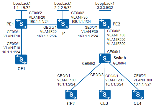
Figure 1 shows a backbone network built by an enterprise. Site1 connects to PE1 through CE1 and then connects to the backbone network. Site2 connects to PE2 through CE2, CE3, and CE4 and then connects to the backbone network. Martini VPLS is configured between PE1 and PE2 to realize Layer 2 service forwarding between users. CE2, CE3, and CE4 are used to connect different user services to the network. The enterprise requires forwarding isolation between CE3 and CE4, but wants CE2 to communicate with both CE3 and CE4.
Configuration Roadmap
The configuration roadmap is as follows:
Configure VLANs and IP addresses for interfaces.
Configure OSPF.
Configure MPLS LDP.
Establish a remote MPLS LDP session.
Configure Martini VPLS.
Configure forwarding isolation between AC interfaces to realize forwarding isolation between CE3 and CE4, while enabling CE2 to communicate with both CE3 and CE4.
Procedure
- Configure VLANs and IP addresses for interfaces.
# Configure CE2. The configurations of CE1, CE3, and CE4 are similar to the configuration of CE2, and are not mentioned here.
<HUAWEI> system-view
[HUAWEI] sysname CE2
[CE2] vlan batch 100
[CE2] interface vlanif 100
[CE2-Vlanif100] ip address 10.1.1.2 255.255.255.0
[CE2-Vlanif100] quit
[CE2] interface gigabitethernet 0/0/1
[CE2-GigabitEthernet0/0/1] port link-type trunk
[CE2-GigabitEthernet0/0/1] port trunk allow-pass vlan 100
[CE2-GigabitEthernet0/0/1] quit
# Configure Switch.
<HUAWEI> system-view
[HUAWEI] sysname Switch
[Switch] vlan batch 100 200 300
[Switch] interface gigabitethernet 0/0/1
[Switch-GigabitEthernet0/0/1] port link-type trunk
[Switch-GigabitEthernet0/0/1] port trunk allow-pass vlan 100 200 300
[Switch-GigabitEthernet0/0/1] quit
[Switch] interface gigabitethernet 0/0/2
[Switch-GigabitEthernet0/0/2] port link-type trunk
[Switch-GigabitEthernet0/0/2] port trunk allow-pass vlan 100
[Switch-GigabitEthernet0/0/2] quit
[Switch] interface gigabitethernet 0/0/3
[Switch-GigabitEthernet0/0/3] port link-type trunk
[Switch-GigabitEthernet0/0/3] port trunk allow-pass vlan 200
[Switch-GigabitEthernet0/0/3] quit
[Switch] interface gigabitethernet 0/0/4
[Switch-GigabitEthernet0/0/4] port link-type trunk
[Switch-GigabitEthernet0/0/4] port trunk allow-pass vlan 300
[Switch-GigabitEthernet0/0/4] quit
# Configure PE2. The configurations of PE1 and the P are similar to the configuration of PE2, and are not mentioned here.
<HUAWEI> system-view
[HUAWEI] sysname PE2
[PE2] vlan batch 30 100 200 300
[PE2] interface vlanif 30
[PE2-Vlanif30] ip address 169.1.1.2 255.255.255.0
[PE2-Vlanif30] quit
[PE2] interface gigabitethernet 0/0/1
[PE2-GigabitEthernet0/0/1] port link-type trunk
[PE2-GigabitEthernet0/0/1] port trunk allow-pass vlan 30
[PE2-GigabitEthernet0/0/1] quit
[PE2] interface gigabitethernet 0/0/2
[PE2-GigabitEthernet0/0/2] port link-type trunk
[PE2-GigabitEthernet0/0/2] port trunk allow-pass vlan 100 200 300
[PE2-GigabitEthernet0/0/2] quit

The AC-side and PW-side physical interfaces of a PE cannot be added to the same VLAN; otherwise, a loop may occur.
- Configure OSPF on PE1, the P, and PE2.
# Configure PE1. The configurations of PE2 and the P are similar to the configuration of PE1, and are not mentioned here.
[PE1] interface loopback 1
[PE1-LoopBack1] ip address 1.1.1.9 255.255.255.255
[PE1-LoopBack1] quit
[PE1] ospf 1
[PE1-ospf-1] area 0.0.0.0
[PE1-ospf-1-area-0.0.0.0] network 1.1.1.9 0.0.0.0
[PE1-ospf-1-area-0.0.0.0] network 168.1.1.0 0.0.0.255
[PE1-ospf-1-area-0.0.0.0] quit
[PE1-ospf-1] quit
After the configuration is complete, run the display ip routing-table command on PE1, PE2, and the P. You can view the routes that the devices have learned from each other.
- Configure basic MPLS functions and LDP on PE1, the P, and
PE2.
# Configure PE1. The configurations of PE2 and the P are similar to the configuration of PE1, and are not mentioned here.
[PE1] mpls lsr-id 1.1.1.9
[PE1] mpls
[PE1-mpls] quit
[PE1] mpls ldp
[PE1-mpls-ldp] quit
[PE1] interface vlanif 20
[PE1-Vlanif20] mpls
[PE1-Vlanif20] mpls ldp
[PE1-Vlanif20] quit
After the configuration is complete, run the display mpls ldp session command on PE1, PE2 and the P. You can view that Status of the peer relationship between PE1 and the P and between PE2 and the P is Operational, which indicates that the peer relationships have been established. Run the display mpls lsp command to view the LSP information.
- Establish a remote LDP session between the PEs.
# Configure PE1.
[PE1] mpls ldp remote-peer 3.3.3.9
[PE1-mpls-ldp-remote-3.3.3.9] remote-ip 3.3.3.9
[PE1-mpls-ldp-remote-3.3.3.9] quit
# Configure PE2.
[PE2] mpls ldp remote-peer 1.1.1.9
[PE2-mpls-ldp-remote-1.1.1.9] remote-ip 1.1.1.9
[PE2-mpls-ldp-remote-1.1.1.9] quit
After the configuration is complete, run the display mpls ldp session command on PE1 or PE2. You can view that Status of the peer relationship between PE1 and PE2 is Operational, indicating that a remote LDP session has been established.
- Enable MPLS L2VPN on the PEs.
# Configure PE1.
[PE1] mpls l2vpn
[PE1-l2vpn] quit
# Configure PE2.
[PE2] mpls l2vpn
[PE2-l2vpn] quit
- Configure LDP VPLS on the PEs.
# Configure PE1.
[PE1] vsi a2 static
[PE1-vsi-a2] pwsignal ldp
[PE1-vsi-a2-ldp] vsi-id 2
[PE1-vsi-a2-ldp] peer 3.3.3.9
[PE1-vsi-a2-ldp] quit
[PE1-vsi-a2] quit
# Configure PE2.
[PE2] vsi a2 static
[PE2-vsi-a2] pwsignal ldp
[PE2-vsi-a2-ldp] vsi-id 2
[PE2-vsi-a2-ldp] peer 1.1.1.9
[PE2-vsi-a2-ldp] quit
[PE2-vsi-a2] quit
- Bind interfaces to the VSI on the PEs.
# Configure PE1.
[PE1] interface vlanif 10
[PE1-Vlanif10] l2 binding vsi a2
[PE1-Vlanif10] quit
# Configure PE2.
[PE2] interface vlanif 100
[PE2-Vlanif100] l2 binding vsi a2
[PE2-Vlanif100] quit
[PE2] interface vlanif 200
[PE2-Vlanif200] l2 binding vsi a2
[PE2-Vlanif200] quit
[PE2] interface vlanif 300
[PE2-Vlanif300] l2 binding vsi a2
[PE2-Vlanif300] quit
- Configure forwarding isolation between AC interfaces on
PE2 and set the VSI attribute of VLANIF100 to hub. The settings allow
CE2 to communicate with both CE3 and CE4 but isolate CE3 and CE4.
# Configure forwarding isolation between AC interfaces in the VSI a2.
[PE2] vsi a2
[PE2-vsi-a2] isolate spoken
[PE2-vsi-a2] quit
# Set the VSI attribute of VLANIF100 to hub.
[PE2] interface vlanif 100
[PE2-Vlanif100] hub-mode enable
[PE2-Vlanif100] quit
- Verify the configuration.
# After the network becomes stable, run the display vsi name a2 verbose command on PE1. You can view that VSI a2 sets up a PW to PE2, and the status of the VSI is Up.
[PE1] display vsi name a2 verbose

 ***VSI Name               : a2
    Administrator VSI      : no
    Isolate Spoken         : disable
    VSI Index              : 0
    PW Signaling           : ldp
    Member Discovery Style : static
    PW MAC Learn Style     : unqualify
    Encapsulation Type     : vlan
    MTU                    : 1500
    Diffserv Mode          : uniform
    Mpls Exp               : --
    DomainId               : 255
    Domain Name            :
    Ignore AcState         : disable
    P2P VSI                : disable
    Create Time            : 0 days, 0 hours, 7 minutes, 18 seconds
    VSI State              : up

    VSI ID                 : 2
   *Peer Router ID         : 3.3.3.9
    Negotiation-vc-id      : 2
    primary or secondary   : primary
    ignore-standby-state   : no
    VC Label               : 1028
    Peer Type              : dynamic
    Session                : up
    Tunnel ID              : 0x48000003
    Broadcast Tunnel ID    : 0x48000003
    Broad BackupTunnel ID  : 0x0
    CKey                   : 2
    NKey                   : 1
    Stp Enable             : 0
    PwIndex                : 0
    Control Word           : disable
    BFD for PW             : unavailable

    Interface Name         : Vlanif10
    State                  : up
    Access Port            : false
    Last Up Time           : 2017/12/25 15:05:00
    Total Up Time          : 0 days, 0 hours, 4 minutes, 27 seconds

  **PW Information:

   *Peer Ip Address        : 3.3.3.9
    PW State               : up
    Local VC Label         : 1028
    Remote VC Label        : 1026
    Remote Control Word    : disable
    PW Type                : label
    Local  VCCV            : alert lsp-ping bfd
    Remote VCCV            : alert lsp-ping bfd
    Tunnel ID              : 0x48000003
    Broadcast Tunnel ID    : 0x48000003
    Broad BackupTunnel ID  : 0x0
    Ckey                   : 0x2
    Nkey                   : 0x1
    Main PW Token          : 0x48000003
    Slave PW Token         : 0x0
    Tnl Type               : LSP
    OutInterface           : Vlanif20
    Backup OutInterface    :
    Stp Enable             : 0
    PW Last Up Time        : 2017/12/25 15:05:23
    PW Total Up Time       : 0 days, 0 hours, 4 minutes, 18 seconds
# You can successfully ping CE2, CE3, and CE4 on CE1. The following shows the ping result from CE1 to CE2.
[CE1] ping 10.1.1.2
  PING 10.1.1.2: 56  data bytes, press CTRL_C to break
    Reply from 10.1.1.2: bytes=56 Sequence=1 ttl=254 time=1 ms
    Reply from 10.1.1.2: bytes=56 Sequence=2 ttl=254 time=1 ms
    Reply from 10.1.1.2: bytes=56 Sequence=3 ttl=254 time=1 ms
    Reply from 10.1.1.2: bytes=56 Sequence=4 ttl=254 time=1 ms
    Reply from 10.1.1.2: bytes=56 Sequence=5 ttl=254 time=1 ms

  --- 10.1.1.2 ping statistics ---
    5 packet(s) transmitted
    5 packet(s) received
    0.00% packet loss
    round-trip min/avg/max = 1/1/1 ms
# You can successfully ping CE3 and CE4 on CE2. The following shows the ping result from CE2 to CE3.
[CE2] ping 10.1.1.3
  PING 10.1.1.3: 56  data bytes, press CTRL_C to break
    Reply from 10.1.1.3: bytes=56 Sequence=1 ttl=254 time=1 ms
    Reply from 10.1.1.3: bytes=56 Sequence=2 ttl=254 time=1 ms
    Reply from 10.1.1.3: bytes=56 Sequence=3 ttl=254 time=1 ms
    Reply from 10.1.1.3: bytes=56 Sequence=4 ttl=254 time=1 ms
    Reply from 10.1.1.3: bytes=56 Sequence=5 ttl=254 time=1 ms

  --- 10.1.1.3 ping statistics ---
    5 packet(s) transmitted
    5 packet(s) received
    0.00% packet loss
    round-trip min/avg/max = 1/1/1 ms
# CE3 and CE4 cannot ping each other. The following shows the ping result from CE3 to CE4.
[CE3] ping 10.1.1.4
  PING 10.1.1.4: 56  data bytes, press CTRL_C to break
    Request time out
    Request time out
    Request time out
    Request time out
    Request time out

  --- 10.1.1.4 ping statistics ---
    5 packet(s) transmitted
    0 packet(s) received
    100.00% packet loss
Configuration Files
CE1 configuration file
#
sysname CE1
#
vlan batch 10
#
interface Vlanif10
 ip address 10.1.1.1 255.255.255.0
#
interface GigabitEthernet0/0/1
 port link-type trunk
 port trunk allow-pass vlan 10
#
return
CE2 configuration file
#
sysname CE2
#
vlan batch 100
#
interface Vlanif100
 ip address 10.1.1.2 255.255.255.0
#
interface GigabitEthernet0/0/1
 port link-type trunk
 port trunk allow-pass vlan 100
#
return
CE3 configuration file
#
sysname CE3
#
vlan batch 200
#
interface Vlanif200
 ip address 10.1.1.3 255.255.255.0
#
interface GigabitEthernet0/0/1
 port link-type trunk
 port trunk allow-pass vlan 200
#
return
CE4 configuration file
#
sysname CE4
#
vlan batch 300
#
interface Vlanif300
 ip address 10.1.1.4 255.255.255.0
#
interface GigabitEthernet0/0/1
 port link-type trunk
 port trunk allow-pass vlan 300
#
return
Switch configuration file
#
sysname Switch
#
vlan batch 100 200 300
#
interface GigabitEthernet0/0/1
 port link-type trunk
 port trunk allow-pass vlan 100 200 300
#
interface GigabitEthernet0/0/2
 port link-type trunk
 port trunk allow-pass vlan 100
#
interface GigabitEthernet0/0/3
 port link-type trunk
 port trunk allow-pass vlan 200
#
interface GigabitEthernet0/0/4
 port link-type trunk
 port trunk allow-pass vlan 300
#
return
PE1 configuration file
#
sysname PE1
#
vlan batch 10 20
#
mpls lsr-id 1.1.1.9
mpls
#
mpls l2vpn
#
vsi a2 static
 pwsignal ldp
  vsi-id 2
  peer 3.3.3.9
#
mpls ldp
#
mpls ldp remote-peer 3.3.3.9
 remote-ip 3.3.3.9
#
interface Vlanif10
 l2 binding vsi a2
#
interface Vlanif20
 ip address 168.1.1.1 255.255.255.0
 mpls
 mpls ldp
#
interface GigabitEthernet0/0/1
 port link-type trunk
 port trunk allow-pass vlan 10
#
interface GigabitEthernet0/0/2
 port link-type trunk
 port trunk allow-pass vlan 20
#
interface LoopBack1
 ip address 1.1.1.9 255.255.255.255
#
ospf 1
 area 0.0.0.0
  network 1.1.1.9 0.0.0.0
  network 168.1.1.0 0.0.0.255
#
return
P configuration file
#
sysname P
#
vlan batch 20 30
#
mpls lsr-id 2.2.2.9
mpls
#
mpls ldp
#
interface Vlanif20
 ip address 168.1.1.2 255.255.255.0
 mpls
 mpls ldp
#
interface Vlanif30
 ip address 169.1.1.1 255.255.255.0
 mpls
 mpls ldp
#
interface GigabitEthernet0/0/1
 port link-type trunk
 port trunk allow-pass vlan 20
#
interface GigabitEthernet0/0/2
 port link-type trunk
 port trunk allow-pass vlan 30
#
interface LoopBack1
 ip address 2.2.2.9 255.255.255.255
#
ospf 1
 area 0.0.0.0
  network 2.2.2.9 0.0.0.0
  network 168.1.1.0 0.0.0.255
  network 169.1.1.0 0.0.0.255
#
return
PE2 configuration file
#
sysname PE2
#
vlan batch 30 100 200 300
#
mpls lsr-id 3.3.3.9
mpls
#
mpls l2vpn
#
vsi a2 static
 pwsignal ldp
  vsi-id 2
  peer 1.1.1.9
 isolate spoken
#
mpls ldp
#
mpls ldp remote-peer 1.1.1.9
 remote-ip 1.1.1.9
#
interface Vlanif30
 ip address 169.1.1.2 255.255.255.0
 mpls
 mpls ldp
#
interface Vlanif100
 l2 binding vsi a2
 hub-mode enable
#
interface Vlanif200
 l2 binding vsi a2
#
interface Vlanif300
 l2 binding vsi a2
#
interface GigabitEthernet0/0/1
 port link-type trunk
 port trunk allow-pass vlan 30
#
interface GigabitEthernet0/0/2
 port link-type trunk
 port trunk allow-pass vlan 100 200 300
#
interface LoopBack1
 ip address 3.3.3.9 255.255.255.255
#
ospf 1
 area 0.0.0.0
  network 3.3.3.9 0.0.0.0
  network 169.1.1.0 0.0.0.255
#
return