Example for Configuring Point-to-Multipoint VPLS in Martini Mode
Networking Requirements
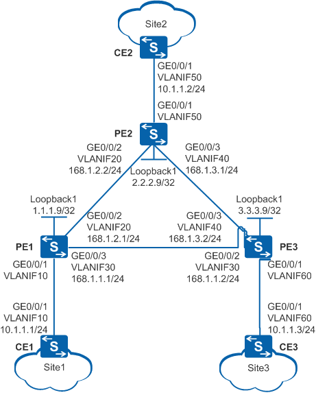
In Figure 1, an enterprise builds a backbone network and has three branch sites. Site1 connects to PE1 on the backbone network through CE1. Site2 connects to PE2 on the backbone network through CE2. Site3 connects to PE3 on the backbone network through CE3. Users at Site1, Site2, and Site3 need to communicate at Layer 2.
Configuration Roadmap
Configure VLANs and IP addresses for interfaces.
- Configure an IGP. In this example, OSPF is used.
- Configure MPLS LDP.
- Establish a remote MPLS LDP session.
- Configure Martini VPLS.
Procedure
- Configure VLANs and IP addresses for interfaces.
# Configure CE1. The configurations of CE2, CE3, PE1, PE2, and PE3 are similar to that of CE1.
<HUAWEI> system-view
[HUAWEI] sysname CE1
[CE1] vlan 10
[CE1-vlan10] quit
[CE1] interface vlanif 10
[CE1-Vlanif10] ip address 10.1.1.1 255.255.255.0
[CE1-Vlanif10] quit
[CE1] interface gigabitethernet 0/0/1
[CE1-GigabitEthernet0/0/1] port link-type trunk
[CE1-GigabitEthernet0/0/1] port trunk allow-pass vlan 10
[CE1-GigabitEthernet0/0/1] quit

The AC-side and PW-side physical interfaces of a PE cannot be added to the same VLAN; otherwise, a loop may occur.
- Configure OSPF on PE1, PE2, and PE3.
When configuring OSPF, advertise the 32-bit IP address of the loopback interface (LSR IDs) on PE1, PE2, and PE3.
# Configure PE1. The configurations of PE2 and PE3 are similar to that of PE1.
[PE1] interface loopback 1
[PE1-LoopBack1] ip address 1.1.1.9 255.255.255.255
[PE1-LoopBack1] quit
[PE1] ospf 1 router-id 1.1.1.9
[PE1-ospf-1] area 0.0.0.0
[PE1-ospf-1-area-0.0.0.0] network 1.1.1.9 0.0.0.0
[PE1-ospf-1-area-0.0.0.0] network 168.1.1.0 0.0.0.255
[PE1-ospf-1-area-0.0.0.0] network 168.1.2.0 0.0.0.255
[PE1-ospf-1-area-0.0.0.0] quit
[PE1-ospf-1] quit
After the configuration is complete, run the display ip routing-table command on PE1, PE2, and PE3. The command output shows that PE1, PE2, and PE3 have learned routes from each other.
- Configure basic MPLS functions and LDP on PE1, PE2, and PE3.
# Configure PE1. The configurations of PE2 and PE3 are similar to that of PE1.
[PE1] mpls lsr-id 1.1.1.9
[PE1] mpls
[PE1-mpls] quit
[PE1] mpls ldp
[PE1-mpls-ldp] quit
[PE1] interface vlanif 20
[PE1-Vlanif20] mpls
[PE1-Vlanif20] mpls ldp
[PE1-Vlanif20] quit
[PE1] interface vlanif 30
[PE1-Vlanif30] mpls
[PE1-Vlanif30] mpls ldp
[PE1-Vlanif30] quit
# After the configuration is complete, run the display mpls ldp session command on PE1, PE2, and PE3. The command output shows that the Status field of the peer relationships between PE1, PE2, and PE3 is Operational, indicating that the peer relationships have been established. The following uses the command output on PE1 as an example.
[PE1] display mpls ldp session

 LDP Session(s) in Public Network
 Codes: LAM(Label Advertisement Mode), SsnAge Unit(DDDD:HH:MM)
 A '*' before a session means the session is being deleted.
 ------------------------------------------------------------------------------
 PeerID             Status      LAM  SsnRole  SsnAge      KASent/Rcv
 ------------------------------------------------------------------------------
 2.2.2.9:0          Operational DU   Passive  0004:03:36  23906/23906
 3.3.3.9:0          Operational DU   Passive  0004:03:41  23928/23927
 ------------------------------------------------------------------------------
 TOTAL: 2 session(s) Found.
# After the configuration is complete, run the display mpls lsp command on PE1, PE2, and PE3 to check information about the established LSPs. The following uses the command output on PE1 as an example.
[PE1] display mpls lsp Flag after Out IF: (I) - LSP Is Only Iterated by RLFA ------------------------------------------------------------------------------- LSP Information: LDP LSP ------------------------------------------------------------------------------- FEC In/Out Label In/Out IF Vrf Name 1.1.1.9/32 3/NULL -/- 3.3.3.9/32 NULL/3 -/Vlanif30 3.3.3.9/32 1024/3 -/Vlanif30 2.2.2.9/32 NULL/1025 -/Vlanif30 2.2.2.9/32 1025/1025 -/Vlanif30 - Establish a remote LDP session between PEs.
# Configure PE1.
[PE1] mpls ldp remote-peer 2.2.2.9
[PE1-mpls-ldp-remote-2.2.2.9] remote-ip 2.2.2.9
[PE1-mpls-ldp-remote-2.2.2.9] quit
[PE1] mpls ldp remote-peer 3.3.3.9
[PE1-mpls-ldp-remote-3.3.3.9] remote-ip 3.3.3.9
[PE1-mpls-ldp-remote-3.3.3.9] quit
# Configure PE2.
[PE2] mpls ldp remote-peer 1.1.1.9
[PE2-mpls-ldp-remote-1.1.1.9] remote-ip 1.1.1.9
[PE2-mpls-ldp-remote-1.1.1.9] quit
[PE2] mpls ldp remote-peer 3.3.3.9
[PE2-mpls-ldp-remote-3.3.3.9] remote-ip 3.3.3.9
[PE2-mpls-ldp-remote-3.3.3.9] quit
# Configure PE3.
[PE3] mpls ldp remote-peer 1.1.1.9
[PE3-mpls-ldp-remote-1.1.1.9] remote-ip 1.1.1.9
[PE3-mpls-ldp-remote-1.1.1.9] quit
[PE3] mpls ldp remote-peer 2.2.2.9
[PE3-mpls-ldp-remote-2.2.2.9] remote-ip 2.2.2.9
[PE3-mpls-ldp-remote-2.2.2.9] quit
After the configuration is complete, run the display mpls ldp session command on PE1, PE2, and PE3. The command output shows that the Status of the peer relationships between PE1, PE2, and PE3 is Operational, indicating that the remote peer relationships have been established.
- Enable MPLS L2VPN on PEs.
# Configure PE1.
[PE1] mpls l2vpn
[PE1-l2vpn] quit
# Configure PE2.
[PE2] mpls l2vpn
[PE2-l2vpn] quit
# Configure PE3.
[PE3] mpls l2vpn
[PE3-l2vpn] quit
- Configure LDP VPLS on PEs.
# Configure PE1.
[PE1] vsi company static
[PE1-vsi-company] pwsignal ldp
[PE1-vsi-company-ldp] vsi-id 1
[PE1-vsi-company-ldp] peer 2.2.2.9
[PE1-vsi-company-ldp] peer 3.3.3.9
[PE1-vsi-company-ldp] quit
[PE1-vsi-company] quit
# Configure PE2.
[PE2] vsi company static
[PE2-vsi-company] pwsignal ldp
[PE2-vsi-company-ldp] vsi-id 1
[PE2-vsi-company-ldp] peer 1.1.1.9
[PE1-vsi-company-ldp] peer 3.3.3.9
[PE2-vsi-company-ldp] quit
[PE2-vsi-company] quit
# Configure PE3.
[PE3] vsi company static
[PE3-vsi-company] pwsignal ldp
[PE3-vsi-company-ldp] vsi-id 1
[PE3-vsi-company-ldp] peer 1.1.1.9
[PE3-vsi-company-ldp] peer 2.2.2.9
[PE3-vsi-company-ldp] quit
[PE3-vsi-company] quit
- Bind the VSI to PE interfaces.
# Configure PE1.
[PE1] interface vlanif 10
[PE1-Vlanif10] l2 binding vsi company
[PE1-Vlanif10] quit
# Configure PE2.
[PE2] interface vlanif 50
[PE2-Vlanif50] l2 binding vsi company
[PE2-Vlanif50] quit
# Configure PE3.
[PE3] interface vlanif 60
[PE3-Vlanif60] l2 binding vsi company
[PE3-Vlanif60] quit
- Verify the configuration.
# After the network becomes stable, run the display vsi name company verbose command on PE1. The command output shows that a PW to PE2 and a PW to PE3 have been established in the VSI named company, and the VSI status is Up.
[PE1] display vsi name company verbose

 ***VSI Name               : company
    Administrator VSI      : no
    Isolate Spoken         : disable
    VSI Index              : 0
    PW Signaling           : ldp
    Member Discovery Style : static
    PW MAC Learn Style     : unqualify
    Encapsulation Type     : vlan
    MTU                    : 1500
    Diffserv Mode          : uniform
    Mpls Exp               : --
    DomainId               : 255
    Domain Name            :
    Ignore AcState         : disable
    P2P VSI                : disable
    Create Time            : 0 days, 0 hours, 1 minutes, 25 seconds
    VSI State              : up

    VSI ID                 : 1
   *Peer Router ID         : 2.2.2.9
    Negotiation-vc-id      : 1
    primary or secondary   : primary
    ignore-standby-state   : no
    VC Label               : 1026
    Peer Type              : dynamic
    Session                : up
    Tunnel ID              : 0x48000003
    Broadcast Tunnel ID    : 0x48000003
    Broad BackupTunnel ID  : 0x0
    CKey                   : 2
    NKey                   : 1
    Stp Enable             : 0
    PwIndex                : 0
    Control Word           : disable
    BFD for PW             : unavailable
   *Peer Router ID         : 3.3.3.9
    Negotiation-vc-id      : 1
    primary or secondary   : primary
    ignore-standby-state   : no
    VC Label               : 1027
    Peer Type              : dynamic
    Session                : up
    Tunnel ID              : 0x48000001
    Broadcast Tunnel ID    : 0x48000001
    Broad BackupTunnel ID  : 0x0
    CKey                   : 4
    NKey                   : 3
    Stp Enable             : 0
    PwIndex                : 0
    Control Word           : disable
    BFD for PW             : unavailable

    Interface Name         : Vlanif10
    State                  : up
    Access Port            : false
    Last Up Time           : 2020/03/19 07:59:32
    Total Up Time          : 0 days, 0 hours, 0 minutes, 54 seconds

  **PW Information:

   *Peer Ip Address        : 2.2.2.9
    PW State               : up
    Local VC Label         : 1026
    Remote VC Label        : 1026
    Remote Control Word    : disable
    PW Type                : label
    Local  VCCV            : alert lsp-ping bfd
    Remote VCCV            : alert lsp-ping bfd
    Tunnel ID              : 0x48000003
    Broadcast Tunnel ID    : 0x48000003
    Broad BackupTunnel ID  : 0x0
    Ckey                   : 0x2
    Nkey                   : 0x1
    Main PW Token          : 0x48000003
    Slave PW Token         : 0x0
    Tnl Type               : LSP
    OutInterface           : Vlanif30
    Backup OutInterface    :
    Stp Enable             : 0
    PW Last Up Time        : 2020/03/19 07:59:46
    PW Total Up Time       : 0 days, 0 hours, 0 minutes, 40 seconds
   *Peer Ip Address        : 3.3.3.9
    PW State               : up
    Local VC Label         : 1027
    Remote VC Label        : 1028
    Remote Control Word    : disable
    PW Type                : label
    Local  VCCV            : alert lsp-ping bfd
    Remote VCCV            : alert lsp-ping bfd
    Tunnel ID              : 0x48000001
    Broadcast Tunnel ID    : 0x48000001
    Broad BackupTunnel ID  : 0x0
    Ckey                   : 0x4
    Nkey                   : 0x3
    Main PW Token          : 0x48000001
    Slave PW Token         : 0x0
    Tnl Type               : LSP
    OutInterface           : Vlanif30
    Backup OutInterface    :
    Stp Enable             : 0
    PW Last Up Time        : 2020/03/19 08:00:01
    PW Total Up Time       : 0 days, 0 hours, 0 minutes, 25 seconds
CE1, CE2, and CE3 can ping each other successfully. The following information shows that CE1 (10.1.1.1) successfully pings CE3 (10.1.1.3).
[CE1] ping 10.1.1.3
  PING 10.1.1.3: 56  data bytes, press CTRL_C to break
    Reply from 10.1.1.3: bytes=56 Sequence=1 ttl=254 time=1 ms
    Reply from 10.1.1.3: bytes=56 Sequence=2 ttl=254 time=1 ms
    Reply from 10.1.1.3: bytes=56 Sequence=3 ttl=254 time=1 ms
    Reply from 10.1.1.3: bytes=56 Sequence=4 ttl=254 time=1 ms
    Reply from 10.1.1.3: bytes=56 Sequence=5 ttl=254 time=1 ms

  --- 10.1.1.3 ping statistics ---
    5 packet(s) transmitted
    5 packet(s) received
    0.00% packet loss
    round-trip min/avg/max = 1/1/1 ms
Configuration Files
CE1 configuration file
#
sysname CE1
#
vlan batch 10
#
interface Vlanif10
 ip address 10.1.1.1 255.255.255.0
#
interface GigabitEthernet0/0/1
 port link-type trunk
 port trunk allow-pass vlan 10
#
return
CE2 configuration file
# sysname CE2 # vlan batch 50 # interface Vlanif50 ip address 10.1.1.2 255.255.255.0 # interface GigabitEthernet0/0/1 port link-type trunk port trunk allow-pass vlan 50 # return- CE3 configuration file
#
sysname CE3
#
vlan batch 60
#
interface Vlanif60
 ip address 10.1.1.3 255.255.255.0
#
interface GigabitEthernet0/0/1
 port link-type trunk
 port trunk allow-pass vlan 60
#
return
PE1 configuration file
#
sysname PE1
#
vlan batch 10 20 30
#
mpls lsr-id 1.1.1.9
mpls
#
mpls l2vpn
#
vsi company static
 pwsignal ldp
  vsi-id 1
  peer 2.2.2.9
  peer 3.3.3.9
#
mpls ldp
#
mpls ldp remote-peer 2.2.2.9
 remote-ip 2.2.2.9
#
mpls ldp remote-peer 3.3.3.9
 remote-ip 3.3.3.9
#
interface Vlanif10
 l2 binding vsi company
#
interface Vlanif20
 ip address 168.1.2.1 255.255.255.0
 mpls
 mpls ldp
#
interface Vlanif30
 ip address 168.1.1.1 255.255.255.0
 mpls
 mpls ldp
#
interface GigabitEthernet0/0/1
 port link-type trunk
 undo port trunk allow-pass vlan 1
 port trunk allow-pass vlan 10
#
interface GigabitEthernet0/0/2
 port link-type trunk
 undo port trunk allow-pass vlan 1
 port trunk allow-pass vlan 20
#
interface GigabitEtherne0/0/3
 port link-type trunk
 undo port trunk allow-pass vlan 1
 port trunk allow-pass vlan 30
#
interface LoopBack1
 ip address 1.1.1.9 255.255.255.255
#
ospf 1 router-id 1.1.1.9
 area 0.0.0.0
  network 1.1.1.9 0.0.0.0
  network 168.1.1.0 0.0.0.255
  network 168.1.2.0 0.0.0.255
#
return
PE2 configuration file
#
sysname PE2
#
vlan batch 20 40 50
#
mpls lsr-id 2.2.2.9
mpls
#
mpls l2vpn
#
vsi company static
 pwsignal ldp
  vsi-id 1
  peer 1.1.1.9
  peer 3.3.3.9
#
mpls ldp
#
mpls ldp remote-peer 1.1.1.9
 remote-ip 1.1.1.9
#
mpls ldp remote-peer 3.3.3.9
 remote-ip 3.3.3.9
#
interface Vlanif20
 ip address 168.1.2.2 255.255.255.0
 mpls
 mpls ldp
#
interface Vlanif40
 ip address 168.1.3.1 255.255.255.0
 mpls
 mpls ldp
#
interface Vlanif50
 l2 binding vsi company
#
interface GigabitEthernet0/0/1
 port link-type trunk
 undo port trunk allow-pass vlan 1
 port trunk allow-pass vlan 50
#
interface GigabitEthernet0/0/2
 port link-type trunk
 undo port trunk allow-pass vlan 1
 port trunk allow-pass vlan 20
#
interface GigabitEthernet0/0/3
 port link-type trunk
 undo port trunk allow-pass vlan 1
 port trunk allow-pass vlan 40
#
interface LoopBack1
 ip address 2.2.2.9 255.255.255.255
#
ospf 1 router-id 2.2.2.9
 area 0.0.0.0
  network 2.2.2.9 0.0.0.0
  network 168.1.2.0 0.0.0.255
  network 168.1.3.0 0.0.0.255
#
return
PE3 configuration file
#
sysname PE3
#
vlan batch 30 40 60
#
mpls lsr-id 3.3.3.9
mpls
#
mpls l2vpn
#
vsi company static
 pwsignal ldp
  vsi-id 1
  peer 1.1.1.9
  peer 2.2.2.9
#
mpls ldp
#
mpls ldp remote-peer 1.1.1.9
 remote-ip 1.1.1.9
#
mpls ldp remote-peer 2.2.2.9
 remote-ip 2.2.2.9
#
interface Vlanif30
 ip address 168.1.1.2 255.255.255.0
 mpls
 mpls ldp
#
interface Vlanif40
 ip address 168.1.3.2 255.255.255.0
 mpls
 mpls ldp
#
interface Vlanif60
 l2 binding vsi company
#
interface GigabitEthernet0/0/1
 port link-type trunk
 undo port trunk allow-pass vlan 1
 port trunk allow-pass vlan 60
#
interface GigabitEthernet0/0/2
 port link-type trunk
 undo port trunk allow-pass vlan 1
 port trunk allow-pass vlan 30
#
interface GigabitEthernet0/0/3
 port link-type trunk
 undo port trunk allow-pass vlan 1
 port trunk allow-pass vlan 40
#
interface LoopBack1
 ip address 3.3.3.9 255.255.255.255
#
ospf 1 router-id 3.3.3.9
 area 0.0.0.0
  network 3.3.3.9 0.0.0.0
  network 168.1.1.0 0.0.0.255
  network 168.1.3.0 0.0.0.255
#
return