Example for Configuring VPLS over TE in Kompella Mode
Networking Requirements
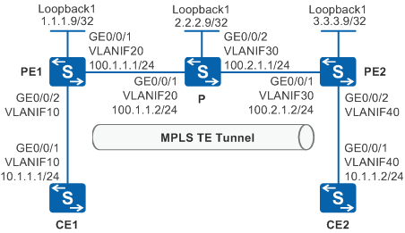
Figure 1 shows a backbone network built by an enterprise. There are a large number of branch sites on the backbone network (only two sites are shown in this example). MPLS TE tunnels can be set up between PEs. Site1 connects to PE1 through CE1 and then connects to the backbone network. Site2 connects to PE2 through CE2 and then connects to the backbone network. Users at Site1 and Site2 need to communicate at Layer 2 and user information needs to be reserved when Layer 2 packets are transmitted over the backbone network.
Configuration Roadmap
The configuration roadmap is as follows:
Configure transparent transmission of Layer 2 packets over the backbone network using VPLS to enable users at Site1 and Site2 to communicate at Layer 2 and reserve user information when Layer 2 packets are transmitted over the backbone network.
Use Kompella VPLS to implement Layer 2 communication between CEs on an enterprise network with many sites and complex network environments.
Configure the IGP routing protocol on the backbone network to implement data transmission on the public network between PEs.
Configure MPLS on PEs on the backbone network to support VPLS.
Establish tunnels for transmitting data between PEs to prevent data from being known by the public network.
Enable MPLS L2VPN on PEs to implement VPLS.
Configure tunnel policies on PEs and apply the policies to VSIs to implement VPLS based on MPLS TE tunnels.
Enable BGP peers to exchange VPLS information between PEs, create a VSI on each PE, specify BGP as the signaling protocol, specify the RD, VPN target, and site of the VSI, and bind AC interfaces to VSIs to implement Kompella VPLS.
Procedure
- Configure VLANs that interfaces belong to.
# Configure PE1. The configuration on P, PE2, CE1, and CE2 is similar to the PE1, and is not mentioned here.
<HUAWEI> system-view
[HUAWEI] sysname PE1
[PE1] vlan batch 10 20
[PE1] interface vlanif 20
[PE1-Vlanif20] ip address 100.1.1.1 255.255.255.0
[PE1-Vlanif20] quit
[PE1] interface gigabitethernet 0/0/1
[PE1-GigabitEthernet0/0/1] port link-type trunk
[PE1-GigabitEthernet0/0/1] port trunk allow-pass vlan 20
[PE1-GigabitEthernet0/0/1] quit
[PE1] interface gigabitethernet 0/0/2
[PE1-GigabitEthernet0/0/2] port link-type trunk
[PE1-GigabitEthernet0/0/2] port trunk allow-pass vlan 10
[PE1-GigabitEthernet0/0/2] quit
- Configure the IGP protocol. OSPF is used in this example.
When configuring OSPF, advertise the 32-bit address of the loopback interface (LSR IDs) on PE1, P, and PE2.
Configure OSPF on PE1, P, and PE2.
# Configure PE1. The configuration on P and PE2 is similar to the PE1, and is not mentioned here.
[PE1] interface loopback 1
[PE1-LoopBack1] ip address 1.1.1.9 255.255.255.255
[PE1-LoopBack1] quit
[PE1] ospf 1
[PE1-ospf-1] area 0.0.0.0
[PE1-ospf-1-area-0.0.0.0] network 1.1.1.9 0.0.0.0
[PE1-ospf-1-area-0.0.0.0] network 100.1.1.0 0.0.0.255
[PE1-ospf-1-area-0.0.0.0] quit
[PE1-ospf-1] quit
After the configuration is complete, run the display ip routing-table command on PE1, P, and PE2. You can view the routes learned by PE1, P, and PE2 from each other.
- Enable MPLS, MPLS TE, MPLS RSVP-TE, and MPLS TE Constraint Shortest Path First (CSPF).
Enable MPLS, MPLS TE, and MPLS RSVP-TE in the system view and interface view of the nodes along the tunnel. In addition, enable MPLS TE CSPF on the ingress.
# Configure PE1.
[PE1] mpls lsr-id 1.1.1.9
[PE1] mpls
[PE1-mpls] mpls te
[PE1-mpls] mpls rsvp-te
[PE1-mpls] mpls te cspf
[PE1-mpls] quit
[PE1] interface vlanif 20
[PE1-Vlanif20] mpls
[PE1-Vlanif20] mpls te
[PE1-Vlanif20] mpls rsvp-te
[PE1-Vlanif20] quit
# Configure the P.
[P] mpls lsr-id 2.2.2.9
[P] mpls
[P-mpls] mpls te
[P-mpls] mpls rsvp-te
[P-mpls] quit
[P] interface vlanif 20
[P-Vlanif20] mpls
[P-Vlanif20] mpls te
[P-Vlanif20] mpls rsvp-te
[P-Vlanif20] quit
[P] interface vlanif 30
[P-Vlanif30] mpls
[P-Vlanif30] mpls te
[P-Vlanif30] mpls rsvp-te
[P-Vlanif30] quit
# Configure PE2.
[PE2] mpls lsr-id 3.3.3.9
[PE2] mpls
[PE2-mpls] mpls te
[PE2-mpls] mpls rsvp-te
[PE2-mpls] mpls te cspf
[PE2-mpls] quit
[PE2] interface vlanif 30
[PE2-Vlanif30] mpls
[PE2-Vlanif30] mpls te
[PE2-Vlanif30] mpls rsvp-te
[PE2-Vlanif30] quit
- Configure OSPF TE on the backbone network.
# Configure PE1.
[PE1] ospf
[PE1-ospf-1] opaque-capability enable
[PE1-ospf-1] area 0.0.0.0
[PE1-ospf-1-area-0.0.0.0] mpls-te enable
[PE1-ospf-1-area-0.0.0.0] quit
[PE1-ospf-1] quit
# Configure P.
[P] ospf
[P-ospf-1] opaque-capability enable
[P-ospf-1] area 0.0.0.0
[P-ospf-1-area-0.0.0.0] mpls-te enable
[P-ospf-1-area-0.0.0.0] quit
[P-ospf-1] quit
# Configure PE2.
[PE2] ospf
[PE2-ospf-1] opaque-capability enable
[PE2-ospf-1] area 0.0.0.0
[PE2-ospf-1-area-0.0.0.0] mpls-te enable
[PE2-ospf-1-area-0.0.0.0] quit
[PE2-ospf-1] quit
- Configure tunnel interfaces.
# Create tunnel interfaces on PEs and specify MPLS TE as the tunnel protocol and RSVP-TE as the signaling protocol.
# Configure PE1.
[PE1] interface tunnel 1
[PE1-Tunnel1] ip address unnumbered interface loopback 1
[PE1-Tunnel1] tunnel-protocol mpls te
[PE1-Tunnel1] destination 3.3.3.9
[PE1-Tunnel1] mpls te tunnel-id 100
[PE1-Tunnel1] mpls te reserved-for-binding
[PE1-Tunnel1] mpls te commit
[PE1-Tunnel1] quit
# Configure PE2.
[PE2] interface tunnel 1
[PE2-Tunnel1] ip address unnumbered interface loopback 1
[PE2-Tunnel1] tunnel-protocol mpls te
[PE2-Tunnel1] destination 1.1.1.9
[PE2-Tunnel1] mpls te tunnel-id 100
[PE2-Tunnel1] mpls te reserved-for-binding
[PE2-Tunnel1] mpls te commit
[PE2-Tunnel1] quit
After the configuration is complete, run the display this interface command in the tunnel interface view. The command output shows that "Line protocol current state" is Up. It indicates that the MPLS TE tunnel is set up successfully.
Run the display tunnel-info all command in the system view. You can see that the TE tunnel whose destination address is the MPLS LSR ID of the peer PE exists. The information displayed on PE1 is used as an example.
[PE1] display tunnel-info all
 * -> Allocated VC Token
Tunnel ID           Type                 Destination           Token
----------------------------------------------------------------------
0x4                 cr lsp                3.3.3.9                109
0x5                 lsp                   3.3.3.9                110
- Establish BGP peers and enable them to exchange VPLS information.
# Configure PE1.
[PE1] bgp 100
[PE1-bgp] peer 3.3.3.9 as-number 100
[PE1-bgp] peer 3.3.3.9 connect-interface loopback 1
[PE1-bgp] vpls-family
[PE1-bgp-af-vpls] peer 3.3.3.9 enable
[PE1-bgp-af-vpls] quit
[PE1-bgp] quit
# Configure PE2.
[PE2] bgp 100
[PE2-bgp] peer 1.1.1.9 as-number 100
[PE2-bgp] peer 1.1.1.9 connect-interface loopback 1
[PE2-bgp] vpls-family
[PE2-bgp-af-vpls] peer 1.1.1.9 enable
[PE2-bgp-af-vpls] quit
[PE2-bgp] quit
- Configure tunnel policies.
# Configure PE1.
[PE1] tunnel-policy policy1
[PE1-tunnel-policy-policy1] tunnel binding destination 3.3.3.9 te tunnel 1
[PE1-tunnel-policy-policy1] quit
# Configure PE2.
[PE2] tunnel-policy policy1 [PE2-tunnel-policy-policy1] tunnel binding destination 1.1.1.9 te tunnel 1 [PE2-tunnel-policy-policy1] quit - Enable MPLS L2VPN on PEs.
# Configure PE1.
[PE1] mpls l2vpn
[PE1-l2vpn] quit
# Configure PE2.
[PE2] mpls l2vpn
[PE2-l2vpn] quit
- Create VSIs on PEs and configure tunnel policies.

Site IDs at both ends of a VSI must be different.
# Configure PE1.
[PE1] vsi bgp1 auto
[PE1-vsi-bgp1] pwsignal bgp
[PE1-vsi-bgp1-bgp] route-distinguisher 100.1.1.1:1
[PE1-vsi-bgp1-bgp] vpn-target 100:1 import-extcommunity
[PE1-vsi-bgp1-bgp] vpn-target 100:1 export-extcommunity
[PE1-vsi-bgp1-bgp] site 1 range 5 default-offset 0
[PE1-vsi-bgp1-bgp] quit
[PE1-vsi-bgp1] tnl-policy policy1
[PE1-vsi-bgp1] quit
# Configure PE2.
[PE2] vsi bgp1 auto
[PE2-vsi-bgp1] pwsignal bgp
[PE2-vsi-bgp1-bgp] route-distinguisher 100.2.1.2:1
[PE2-vsi-bgp1-bgp] vpn-target 100:1 import-extcommunity
[PE2-vsi-bgp1-bgp] vpn-target 100:1 export-extcommunity
[PE2-vsi-bgp1-bgp] site 2 range 5 default-offset 0
[PE2-vsi-bgp1-bgp] quit
[PE2-vsi-bgp1] tnl-policy policy1
[PE2-vsi-bgp1] quit
- Bind interfaces on PEs to VSIs.
# Configure PE1.
[PE1] interface vlanif 10
[PE1-Vlanif10] l2 binding vsi bgp1
[PE1-Vlanif10] quit
# Configure PE2.
[PE2] interface vlanif 40
[PE2-Vlanif40] l2 binding vsi bgp1
[PE2-Vlanif40] quit
- Verify the configuration.
After the network becomes stable, run the display vsi name bgp1 verbose command on PE1, and you can see that VSI bgp1 sets up a PW to PE2, and the status of the VSI is Up.
[PE1] display vsi name bgp1 verbose

 ***VSI Name               : bgp1
    Administrator VSI      : no
    Isolate Spoken         : disable
    VSI Index              : 0
    PW Signaling           : bgp
    Member Discovery Style : auto
    PW MAC Learn Style     : unqualify
    Encapsulation Type     : vlan
    MTU                    : 1500
    Diffserv Mode          : uniform
    Mpls Exp               : --
    DomainId               : 255
    Domain Name            :
    Tunnel Policy Name     : policy1
    Ignore AcState         : disable
    P2P VSI                : disable
    Create Time            : 0 days, 0 hours, 1 minutes, 3 seconds
    VSI State              : up

    BGP RD                 : 100.1.1.1:1
    SiteID/Range/Offset    : 1/5/0
    Import vpn target      : 100:1
    Export vpn target      : 100:1
    Remote Label Block     : 35840/5/0
    Local Label Block      : 0/35840/5/0

    Interface Name         : Vlanif10
    State                  : up
    Access Port            : false
    Last Up Time           : 2018/08/20 20:34:49
    Total Up Time          : 0 days, 0 hours, 1 minutes, 3 seconds

  **PW Information:

   *Peer Ip Address        : 3.3.3.9
    PW State               : up
    Local VC Label         : 35842
    Remote VC Label        : 35841
    PW Type                : label
    Local  VCCV            : alert lsp-ping bfd
    Remote VCCV            : alert lsp-ping bfd
    Tunnel ID              : 0x4
    Broadcast Tunnel ID    : 0x4
    Broad BackupTunnel ID  : 0x0
    Ckey                   : 0x2
    Nkey                   : 0x1
    Main PW Token          : 0x4
    Slave PW Token         : 0x0
    Tnl Type               : CR-LSP
    OutInterface           : Tunnel1
    Backup OutInterface    :
    Stp Enable             : 0
    PW Last Up Time        : 2018/08/20 20:35:51
    PW Total Up Time       : 0 days, 0 hours, 9 minutes, 1 seconds
Run the display vsi pw out-interface vsi bgp1 command on PE1. You can see that the egress interface of the MPLS TE tunnel between 1.1.1.9 and 3.3.3.9 is Tunnel1, and the actual egress interface is VLANIF 20.
[PE1] display vsi pw out-interface vsi bgp1
Total: 1
--------------------------------------------------------------------------------
Vsi Name                        peer            vcid       interface
--------------------------------------------------------------------------------
bgp1                              3.3.3.9         2          Tunnel1
                                                            Vlanif20
CE1 and CE2 can ping each other.
[CE1] ping 10.1.1.2
  PING 10.1.1.2: 56  data bytes, press CTRL_C to break
    Reply from 10.1.1.2: bytes=56 Sequence=1 ttl=255 time=1 ms
    Reply from 10.1.1.2: bytes=56 Sequence=2 ttl=255 time=1 ms
    Reply from 10.1.1.2: bytes=56 Sequence=3 ttl=255 time=1 ms
    Reply from 10.1.1.2: bytes=56 Sequence=4 ttl=255 time=1 ms
    Reply from 10.1.1.2: bytes=56 Sequence=5 ttl=255 time=1 ms

  --- 10.1.1.2 ping statistics ---
    5 packet(s) transmitted
    5 packet(s) received
    0.00% packet loss
    round-trip min/avg/max = 1/1/1 ms
After CE1 pings CE2, run the display interface tunnel 1 command on the PE to view the tunnel interface information, and you can see that the statistics about the packets passing through the interface increase. The information displayed on PE1 is used as an example.
[PE1] display interface tunnel 1
Tunnel1 current state : UP
Line protocol current state : UP
Last line protocol up time : 2018-08-20 14:50:22
Description:
Route Port,The Maximum Transmit Unit is 1500
Internet Address is unnumbered, using address of LoopBack1(1.1.1.9/32)
Encapsulation is TUNNEL, loopback not set
Tunnel destination 3.3.3.9
Tunnel up/down statistics 1
Tunnel protocol/transport MPLS/MPLS, ILM is available,
primary tunnel id is 0x5, secondary tunnel id is 0x0
Current system time: 2018-08-20 15:54:54+00:00
    300 seconds output rate 0 bits/sec, 0 packets/sec
    0 seconds output rate 0 bits/sec, 0 packets/sec
    1249 packets output,  21526 bytes
    0 output error
    0 output drop
    Input bandwidth utilization  :    0%
    Output bandwidth utilization :    0%
Configuration Files
CE1 configuration file
#
sysname CE1
#
vlan batch 10
#
interface Vlanif10
 ip address 10.1.1.1 255.255.255.0
#
interface GigabitEthernet0/0/1
 port link-type trunk
 port trunk allow-pass vlan 10
#
return
PE1 configuration file
#
sysname PE1
#
vlan batch 10 20
#
mpls lsr-id 1.1.1.9
mpls
 mpls te
 mpls rsvp-te
 mpls te cspf
#
mpls l2vpn
#
vsi bgp1 auto
 pwsignal bgp
  route-distinguisher 100.1.1.1:1
  vpn-target 100:1 import-extcommunity
  vpn-target 100:1 export-extcommunity
  site 1 range 5 default-offset 0
 tnl-policy policy1
#
interface Vlanif10
 l2 binding vsi bgp1
#
interface Vlanif20
 ip address 100.1.1.1 255.255.255.0
 mpls
 mpls te
 mpls rsvp-te
#
interface GigabitEthernet0/0/1
 port link-type trunk
 port trunk allow-pass vlan 20
#
interface GigabitEthernet0/0/2
 port link-type trunk
 port trunk allow-pass vlan 10
#
interface LoopBack1
 ip address 1.1.1.9 255.255.255.255
#
interface Tunnel1
 ip address unnumbered interface LoopBack1
 tunnel-protocol mpls te
 destination 3.3.3.9
 mpls te tunnel-id 100
 mpls te reserved-for-binding
 mpls te commit
#
bgp 100
 peer 3.3.3.9 as-number 100
 peer 3.3.3.9 connect-interface LoopBack1
 #
 ipv4-family unicast
  undo synchronization
  peer 3.3.3.9 enable
 #
 vpls-family
  policy vpn-target
  peer 3.3.3.9 enable
#
ospf 1
 opaque-capability enable
 area 0.0.0.0
  network 1.1.1.9 0.0.0.0
  network 100.1.1.0 0.0.0.255
  mpls-te enable
#
tunnel-policy policy1
 tunnel binding destination 3.3.3.9 te Tunnel1
#
return
P configuration file
#
sysname P
#
vlan batch 20 30
#
mpls lsr-id 2.2.2.9
mpls
 mpls te
 mpls rsvp-te
#
interface Vlanif20
 ip address 100.1.1.2 255.255.255.0
 mpls
 mpls te
 mpls rsvp-te
#
interface Vlanif30
 ip address 100.2.1.1 255.255.255.0
 mpls
 mpls te
 mpls rsvp-te
#
interface GigabitEthernet0/0/1
 port link-type trunk
 port trunk allow-pass vlan 20
#
interface GigabitEthernet0/0/2
 port link-type trunk
 port trunk allow-pass vlan 30
#
interface LoopBack1
 ip address 2.2.2.9 255.255.255.255
#
ospf 1
 opaque-capability enable
 area 0.0.0.0
  network 2.2.2.9 0.0.0.0
  network 100.1.1.0 0.0.0.255
  network 100.2.1.0 0.0.0.255
  mpls-te enable
#
return
PE2 configuration file
#
sysname PE2
#
vlan batch 30 40
#
mpls lsr-id 3.3.3.9
mpls
 mpls te
 mpls rsvp-te
 mpls te cspf
#
mpls l2vpn
#
vsi bgp1 auto
 pwsignal bgp
  route-distinguisher 100.2.1.2:1
  vpn-target 100:1 import-extcommunity
  vpn-target 100:1 export-extcommunity
  site 1 range 5 default-offset 0
 tnl-policy policy1
#
interface Vlanif30
 ip address 100.2.1.2 255.255.255.0
 mpls
 mpls te
 mpls rsvp-te
#
interface Vlanif40
 l2 binding vsi bgp1
#
interface GigabitEthernet0/0/1
 port link-type trunk
 port trunk allow-pass vlan 30
#
interface GigabitEthernet0/0/2
 port link-type trunk
 port trunk allow-pass vlan 40
#
interface LoopBack1
 ip address 3.3.3.9 255.255.255.255
#
interface Tunnel1
 ip address unnumbered interface LoopBack1
 tunnel-protocol mpls te
 destination 1.1.1.9
 mpls te tunnel-id 100
 mpls te reserved-for-binding
 mpls te commit
#
bgp 100
 peer 1.1.1.9 as-number 100
 peer 1.1.1.9 connect-interface LoopBack1
 #
 ipv4-family unicast
  undo synchronization
  peer 1.1.1.9 enable
 #
 vpls-family
  policy vpn-target
  peer 1.1.1.9 enable
#
ospf 1
 opaque-capability enable
 area 0.0.0.0
  network 3.3.3.9 0.0.0.0
  network 100.2.1.0 0.0.0.255
  mpls-te enable
#
tunnel-policy policy1
 tunnel binding destination 1.1.1.9 te Tunnel1
#
return
CE2 configuration file
#
sysname CE2
#
vlan batch 40
#
interface Vlanif40
 ip address 10.1.1.2 255.255.255.0
#
interface GigabitEthernet0/0/1
 port link-type trunk
 port trunk allow-pass vlan 40
#
return