Example for Configuring LDP HVPLS
Networking Requirements
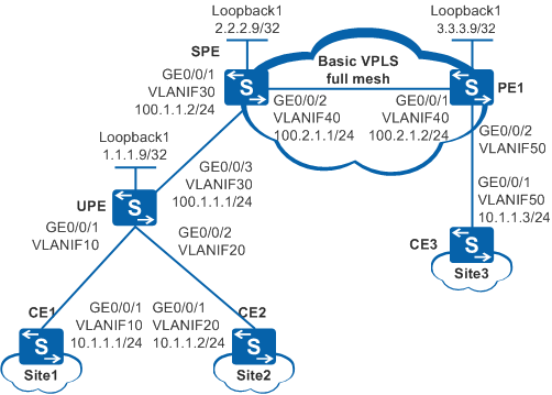
Figure 1 shows a backbone network built by an enterprise. Site1 connects to the UPE through CE1 and then connects to the backbone network. Site2 connects to the UPE through CE2 and then connects to the backbone network. Site3 connects to PE1 through CE3 and then connects to the backbone network. Users at Site1, Site2, and Site3 need to communicate at Layer 2 and user information needs to be reserved when Layer 2 packets are transmitted over the backbone network. It is required that the UPE and SPE are at different layers of the backbone network.
Configuration Roadmap
The configuration roadmap is as follows:
Configure transparent transmission of Layer 2 packets over the backbone network using VPLS to enable users at Site1, Site2, and Site3 to communicate at Layer 2 and reserve user information when Layer 2 packets are transmitted over the backbone network.
Use LDP HVPLS to form a layered network topology and implement Layer 2 communication between CEs for an enterprise network.
Configure the IGP routing protocol on the backbone network to implement data transmission on the public network between PEs.
Configure basic MPLS functions and LDP on the backbone network to support VPLS.
Establish tunnels for transmitting data between PEs to prevent data from being known by the public network.
Enable MPLS L2VPN on PEs to implement VPLS.
Create VSIs on PEs, specify LDP as the signaling protocol, and bind the VSIs to AC interfaces on the UPE and PE1 to implement LDP VPLS.
Specify the UPE as the underlayer PE on the SPE and specify PE1 as the VSI peer, and specify the SPE as the VSI peer both on the UPE and PE1 to implement HVPLS.
Procedure
- Configure VLANs that interfaces belong to.
Configure the VLAN that each interface belongs to and assign IP addresses to interfaces on Switch.
# Configure CE1. The configuration on UPE, SPE, PE1, CE2, and CE3 is similar to the CE1, and is not mentioned here.
<HUAWEI> system-view
[HUAWEI] sysname CE1
[CE1] vlan 10
[CE1-vlan10] quit
[CE1] interface vlanif 10
[CE1-Vlanif10] ip address 10.1.1.1 255.255.255.0
[CE1-Vlanif10] quit
[CE1] interface gigabitethernet 0/0/1
[CE1-GigabitEthernet0/0/1] port link-type trunk
[CE1-GigabitEthernet0/0/1] port trunk allow-pass vlan 10
[CE1-GigabitEthernet0/0/1] quit
Configure VLANs that interfaces belong to and assign IP addresses to interfaces on other Switches by referring to Figure 1. The configuration is similar to the configuration of CE1, and is not mentioned here.

Do not add AC-side physical interfaces and PW-side physical interfaces of a PE to the same VLAN; otherwise, a loop may occur.
- Configure the IGP protocol. OSPF is used in this example.
When configuring OSPF, you need to advertise 32-bit loopback interface addresses (LSR IDs) of the UPE, SPE, and PE1.
Configure OSPF on the UPE, SPE, and PE1.
# Configure the UPE. The configuration on SPE and PE1 is similar to the UPE, and is not mentioned here.
[UPE] interface loopback 1
[UPE-LoopBack1] ip address 1.1.1.9 255.255.255.255
[UPE-LoopBack1] quit
[UPE] ospf 1
[UPE-ospf-1] area 0.0.0.0
[UPE-ospf-1-area-0.0.0.0] network 1.1.1.9 0.0.0.0
[UPE-ospf-1-area-0.0.0.0] network 100.1.1.0 0.0.0.255
[UPE-ospf-1-area-0.0.0.0] quit
[UPE-ospf-1] quit
After the configuration is complete, run the display ip routing-table command on the UPE, SPE, and PE1. You can see that the UPE, SPE, and PE1 have learned the addresses of the loopback interfaces from each other.
- Configure basic MPLS functions and LDP.
Configure basic MPLS functions and LDP on the UPE, SPE, and PE1.
# Configure the UPE. The configuration on SPE and PE1 is similar to the UPE, and is not mentioned here.
[UPE] mpls lsr-id 1.1.1.9
[UPE] mpls
[UPE-mpls] quit
[UPE] mpls ldp
[UPE-mpls-ldp] quit
[UPE] interface vlanif 30
[UPE-Vlanif30] mpls
[UPE-Vlanif30] mpls ldp
[UPE-Vlanif30] quit
After the configuration is complete, run the display mpls ldp session command on the UPE, SPE, and PE1, and you can see that the "Status"of the peer relationship between the UPE and the SPE or between PE1 and the SPE is "Operational", which indicates that the peer relationship has been established. Run the display mpls lsp command to view the LSP status.
- Enable MPLS L2VPN and configure a VSI.
# Configure the UPE.
[UPE] mpls l2vpn
[UPE-l2vpn] quit
[UPE] vsi v123 static
[UPE-vsi-v123] pwsignal ldp
[UPE-vsi-v123-ldp] vsi-id 123
[UPE-vsi-v123-ldp] peer 2.2.2.9
[UPE-vsi-v123-ldp] quit
[UPE-vsi-v123] quit
# Configure the SPE.
[SPE] mpls l2vpn
[SPE-l2vpn] quit
[SPE] vsi v123 static
[SPE-vsi-v123] pwsignal ldp
[SPE-vsi-v123-ldp] vsi-id 123
[SPE-vsi-v123-ldp] peer 3.3.3.9
[SPE-vsi-v123-ldp] peer 1.1.1.9 upe
[SPE-vsi-v123-ldp] quit
[SPE-vsi-v123] quit
# Configure PE1.
[PE1] mpls l2vpn
[PE1-l2vpn] quit
[PE1] vsi v123 static
[PE1-vsi-v123] pwsignal ldp
[PE1-vsi-v123-ldp] vsi-id 123
[PE1-vsi-v123-ldp] peer 2.2.2.9
[PE1-vsi-v123-ldp] quit
[PE1-vsi-v123] quit
- Bind VSIs to interfaces on the UPE and PE1.
# Configure the UPE.
[UPE] interface vlanif 10
[UPE-Vlanif10] l2 binding vsi v123
[UPE-Vlanif10] quit
[UPE] interface vlanif 20
[UPE-Vlanif20] l2 binding vsi v123
[UPE-Vlanif20] quit
# Configure PE1.
[PE1] interface vlanif 50
[PE1-Vlanif50] l2 binding vsi v123
[PE1-Vlanif50] quit
- Verify the configuration.
After the network becomes stable, run the display vsi name v123 verbose command on the SPE, and you can see that the status of the VSI named v123 is Up, and the status of the corresponding PW is also Up.
[SPE] display vsi name v123 verbose

 ***VSI Name               : v123
    Administrator VSI      : no
    Isolate Spoken         : disable
    VSI Index              : 0
    PW Signaling           : ldp
    Member Discovery Style : static
    PW MAC Learn Style     : unqualify
    Encapsulation Type     : vlan
    MTU                    : 1500
    Diffserv Mode          : uniform
    Mpls Exp               : --
    DomainId               : 255
    Domain Name            :
    Ignore AcState         : disable
    P2P VSI                : disable
    Create Time            : 0 days, 0 hours, 1 minutes, 3 seconds
    VSI State              : up

    VSI ID                 : 123
   *Peer Router ID         : 3.3.3.9
    Negotiation-vc-id      : 123
    primary or secondary   : primary
    ignore-standby-state   : no
    VC Label               : 4096
    Peer Type              : dynamic
    Session                : up
    Tunnel ID              : 0x1c5
    Broadcast Tunnel ID    : 0x1c5
    Broad BackupTunnel ID  : 0x0
    CKey                   : 9
    NKey                   : 3
    Stp Enable             : 0
    PwIndex                : 0
    Control Word           : disable
   *Peer Router ID         : 1.1.1.9
    Negotiation-vc-id      : 123
    primary or secondary   : primary
    ignore-standby-state   : no
    VC Label               : 4097
    Peer Type              : dynamic
    Session                : up
    Tunnel ID              : 0x1c3
    Broadcast Tunnel ID    : 0x1c3
    Broad BackupTunnel ID  : 0x0
    CKey                   : 5
    NKey                   : 12
    Stp Enable             : 0
    PwIndex                : 0
    Control Word           : disable

  **PW Information:

   *Peer Ip Address        : 1.1.1.9
    PW State               : up
    Local VC Label         : 4097
    Remote VC Label        : 4096
    Remote Control Word    : disable
    PW Type                : MEHVPLS
    Local  VCCV            : alert lsp-ping bfd
    Remote VCCV            : alert lsp-ping bfd
    Tunnel ID              : 0x1c3
    Broadcast Tunnel ID    : 0x1c3
    Broad BackupTunnel ID  : 0x0
    Ckey                   : 0x5
    Nkey                   : 0xc
    Main PW Token          : 0x1c3
    Slave PW Token         : 0x0
    Tnl Type               : LSP
    OutInterface           : Vlanif30
    Backup OutInterface    :
    Stp Enable             : 0
    PW Last Up Time        : 2014/11/12 11:34:08
    PW Total Up Time       : 0 days, 0 hours, 0 minutes, 22 seconds
   *Peer Ip Address        : 3.3.3.9
    PW State               : up
    Local VC Label         : 4096
    Remote VC Label        : 4096
    Remote Control Word    : disable
    PW Type                : label
    Local  VCCV            : alert lsp-ping bfd
    Remote VCCV            : alert lsp-ping bfd
    Tunnel ID              : 0x1c5
    Broadcast Tunnel ID    : 0x1c5
    Broad BackupTunnel ID  : 0x0
    Ckey                   : 0x9
    Nkey                   : 0x3
    Main PW Token          : 0x1c5
    Slave PW Token         : 0x0
    Tnl Type               : LSP
    OutInterface           : Vlanif40
    Backup OutInterface    :
    Stp Enable             : 0
    PW Last Up Time        : 2014/11/12 11:34:18
    PW Total Up Time       : 0 days, 0 hours, 0 minutes, 12 seconds
CE1, CE2, and CE3 can ping each other. After you run the shutdown command on the interface (to which the VSI is bound) of the UPE or PE1, CE2 and CE3 cannot ping each other. This indicates that data is transmitted through the PW of this VSI.
Configuration Files
UPE configuration file
#
sysname UPE
#
vlan batch 10 20 30
#
mpls lsr-id 1.1.1.9
mpls
#
mpls l2vpn
#
vsi v123 static
 pwsignal ldp
  vsi-id 123
  peer 2.2.2.9
#
mpls ldp
#
interface Vlanif10
 l2 binding vsi v123
#
interface Vlanif20
 l2 binding vsi v123
#
interface Vlanif30
 ip address 100.1.1.1 255.255.255.0
 mpls
 mpls ldp
#
interface GigabitEthernet0/0/1
 port link-type trunk
 port trunk allow-pass vlan 10
#
interface GigabitEthernet0/0/2
 port link-type trunk
 port trunk allow-pass vlan 20
#
interface GigabitEthernet0/0/3
 port link-type trunk
 port trunk allow-pass vlan 30
#
interface LoopBack1
 ip address 1.1.1.9 255.255.255.255
#
ospf 1
 area 0.0.0.0
  network 1.1.1.9 0.0.0.0
  network 100.1.1.0 0.0.0.255
#
return
SPE configuration file
#
sysname SPE
#
vlan batch 30 40
#
mpls lsr-id 2.2.2.9
mpls
#
mpls l2vpn
#
vsi v123 static
 pwsignal ldp
  vsi-id 123
  peer 3.3.3.9
  peer 1.1.1.9 upe
#
mpls ldp
#
interface Vlanif30
 ip address 100.1.1.2 255.255.255.0
 mpls
 mpls ldp
#
interface Vlanif40
 ip address 100.2.1.1 255.255.255.0
 mpls
 mpls ldp
#
interface GigabitEthernet0/0/1
 port link-type trunk
 port trunk allow-pass vlan 30
#
interface GigabitEthernet0/0/2
 port link-type trunk
 port trunk allow-pass vlan 40
#
interface LoopBack1
 ip address 2.2.2.9 255.255.255.255
#
ospf 1
 area 0.0.0.0
  network 2.2.2.9 0.0.0.0
  network 100.1.1.0 0.0.0.255
  network 100.2.1.0 0.0.0.255
#
return
PE1 configuration file
#
sysname PE1
#
vlan batch 40 50
#
mpls lsr-id 3.3.3.9
mpls
#
mpls l2vpn
#
vsi v123 static
 pwsignal ldp
  vsi-id 123
  peer 2.2.2.9
#
mpls ldp
#
interface Vlanif40
 ip address 100.2.1.2 255.255.255.0
 mpls
 mpls ldp
#
interface Vlanif50
 l2 binding vsi v123
#
interface GigabitEthernet0/0/1
 port link-type trunk
 port trunk allow-pass vlan 40
#
interface GigabitEthernet0/0/2
 port link-type trunk
 port trunk allow-pass vlan 50
#
interface LoopBack1
 ip address 3.3.3.9 255.255.255.255
#
ospf 1
 area 0.0.0.0
  network 3.3.3.9 0.0.0.0
  network 100.2.1.0 0.0.0.255
#
return
CE1 configuration file
#
sysname CE1
#
vlan batch 10
#
interface Vlanif10
 ip address 10.1.1.1 255.255.255.0
#
interface GigabitEthernet0/0/1
 port link-type trunk
 port trunk allow-pass vlan 10
#
return
CE2 configuration file
#
sysname CE2
#
vlan batch 20
#
interface Vlanif20
 ip address 10.1.1.2 255.255.255.0
#
interface GigabitEthernet0/0/1
 port link-type trunk
 port trunk allow-pass vlan 20
#
return
CE3 configuration file
#
sysname CE3
#
vlan batch 50
#
interface Vlanif50
 ip address 10.1.1.3 255.255.255.0
#
interface GigabitEthernet0/0/1
 port link-type trunk
 port trunk allow-pass vlan 50
#
return