Example for Configuring a VRRP Group in Load Sharing Mode
Networking Requirements
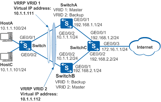
In Figure 1, HostA and HostC are dual-homed to SwitchA and SwitchB through the switch. To reduce the load of data traffic on SwitchA, HostA uses SwitchA as the default gateway to connect to the Internet, and SwitchB functions as the backup gateway. HostC uses SwitchB as the default gateway to connect to the Internet, and SwitchA functions as the backup gateway. This implements load sharing.

In this scenario, to avoid loops, ensure that all connected interfaces have STP disabled and connected interfaces are removed from VLAN 1. If STP is enabled and VLANIF interfaces of switches are used to construct a Layer 3 ring network, an interface on the network will be blocked. As a result, Layer 3 services on the network cannot run normally.
Device |
Interface |
VLANIF Interface |
IP Address |
|---|---|---|---|
SwitchA |
GE0/0/1 |
VLANIF 300 |
192.168.1.1/24 |
GE0/0/2 |
VLANIF 100 |
10.1.1.1/24 |
|
SwitchB |
GE0/0/1 |
VLANIF 200 |
192.168.2.1/24 |
GE0/0/2 |
VLANIF 100 |
10.1.1.2/24 |
|
SwitchC |
GE0/0/1 |
VLANIF 300 |
192.168.1.2/24 |
GE0/0/2 |
VLANIF 200 |
192.168.2.2/24 |
|
GE0/0/3 |
VLANIF 400 |
172.16.1.1/24 |
Configuration Roadmap
The configuration roadmap is as follows:
- Assign an IP address to each interface and configure a routing protocol to ensure network connectivity.
- Create VRRP groups 1 and 2 on SwitchA and SwitchB. In VRRP group 1, configure SwitchA as the master and SwitchB as the backup. In VRRP group 2, configure SwitchB as the master and SwitchA as the backup.
Procedure
- Configure devices to ensure network connectivity.
# Assign an IP address to each interface. SwitchA is used as an example. The configurations of SwitchB and SwitchC are similar to the configuration of SwitchA. For details, see the configuration files.
<HUAWEI> system-view
[HUAWEI] sysname SwitchA
[SwitchA] vlan batch 100 300
[SwitchA] interface gigabitethernet 0/0/1
[SwitchA-GigabitEthernet0/0/1] port link-type hybrid
[SwitchA-GigabitEthernet0/0/1] port hybrid pvid vlan 300
[SwitchA-GigabitEthernet0/0/1] port hybrid untagged vlan 300
[SwitchA-GigabitEthernet0/0/1] quit
[SwitchA] interface gigabitethernet 0/0/2
[SwitchA-GigabitEthernet0/0/2] port link-type hybrid
[SwitchA-GigabitEthernet0/0/2] port hybrid pvid vlan 100
[SwitchA-GigabitEthernet0/0/2] port hybrid untagged vlan 100
[SwitchA-GigabitEthernet0/0/2] quit
[SwitchA] interface vlanif 100
[SwitchA-Vlanif100] ip address 10.1.1.1 24
[SwitchA-Vlanif100] quit
[SwitchA] interface vlanif 300
[SwitchA-Vlanif300] ip address 192.168.1.1 24
[SwitchA-Vlanif300] quit
# Configure Layer 2 transmission on the switch.
<HUAWEI> system-view
[HUAWEI] sysname Switch
[Switch] vlan 100
[Switch-vlan100] quit
[Switch] interface gigabitethernet 0/0/1
[Switch-GigabitEthernet0/0/1] port link-type hybrid
[Switch-GigabitEthernet0/0/1] port hybrid pvid vlan 100
[Switch-GigabitEthernet0/0/1] port hybrid untagged vlan 100
[Switch-GigabitEthernet0/0/1] quit
[Switch] interface gigabitethernet 0/0/2
[Switch-GigabitEthernet0/0/2] port link-type hybrid
[Switch-GigabitEthernet0/0/2] port hybrid pvid vlan 100
[Switch-GigabitEthernet0/0/2] port hybrid untagged vlan 100
[Switch-GigabitEthernet0/0/2] quit
# Configure OSPF between SwitchA, SwitchB, and SwitchC. SwitchA is used as an example. The configurations of SwitchB and SwitchC are similar to the configuration of SwitchA, and are not mentioned here. For details, see the configuration files.
[SwitchA] ospf 1
[SwitchA-ospf-1] area 0
[SwitchA-ospf-1-area-0.0.0.0] network 10.1.1.0 0.0.0.255
[SwitchA-ospf-1-area-0.0.0.0] network 192.168.1.0 0.0.0.255
[SwitchA-ospf-1-area-0.0.0.0] quit
[SwitchA-ospf-1] quit
- Configure VRRP groups.
# Configure VRRP group 1 on SwitchA and SwitchB, set the priority of SwitchA to 120 and the preemption delay to 20s, and set the default priority for SwitchB.
[SwitchA] interface vlanif 100
[SwitchA-Vlanif100] vrrp vrid 1 virtual-ip 10.1.1.111
[SwitchA-Vlanif100] vrrp vrid 1 priority 120
[SwitchA-Vlanif100] vrrp vrid 1 preempt-mode timer delay 20
[SwitchA-Vlanif100] quit
[SwitchB] interface vlanif 100
[SwitchB-Vlanif100] vrrp vrid 1 virtual-ip 10.1.1.111
[SwitchB-Vlanif100] quit
# Configure VRRP group 2 on SwitchA and SwitchB, set the priority of SwitchB to 120 and the preemption delay to 20s, and set the default priority for SwitchA.
[SwitchB] interface vlanif 100
[SwitchB-Vlanif100] vrrp vrid 2 virtual-ip 10.1.1.112
[SwitchB-Vlanif100] vrrp vrid 2 priority 120
[SwitchB-Vlanif100] vrrp vrid 2 preempt-mode timer delay 20
[SwitchB-Vlanif100] quit
[SwitchA] interface vlanif 100
[SwitchA-Vlanif100] vrrp vrid 2 virtual-ip 10.1.1.112
[SwitchA-Vlanif100] quit
- Verify the configuration.
# Run the display vrrp command on SwitchA. You can see that SwitchA is the master in VRRP group 1 and the backup in VRRP group 2.
[SwitchA] display vrrp
  Vlanif100 | Virtual Router 1
    State : Master
    Virtual IP : 10.1.1.111
    Master IP : 10.1.1.1
    PriorityRun : 120
    PriorityConfig : 120
    MasterPriority : 120
    Preempt : YES   Delay Time : 20 s
    TimerRun : 1 s
    TimerConfig : 1 s
    Auth type : NONE
    Virtual MAC : 0000-5e00-0101
    Check TTL : YES
    Config type : normal-vrrp
    Backup-forward : disabled
    Create time : 2012-01-12 20:15:46
    Last change time : 2012-01-12 20:15:46

  Vlanif100 | Virtual Router 2
    State : Backup
    Virtual IP : 10.1.1.112
    Master IP : 10.1.1.2
    PriorityRun : 100
    PriorityConfig : 100
    MasterPriority : 120
    Preempt : YES   Delay Time : 0 s
    TimerRun : 1 s
    TimerConfig : 1 s
    Auth type : NONE
    Virtual MAC : 0000-5e00-0102
    Check TTL : YES
    Config type : normal-vrrp
    Backup-forward : disabled
    Create time : 2012-01-12 20:15:46
    Last change time : 2012-01-12 20:15:46
# Run the display vrrp command on SwitchB. You can see that SwitchB is the backup in VRRP group 1 and the master in VRRP group 2.
[SwitchB] display vrrp
  Vlanif100 | Virtual Router 1
    State : Backup
    Virtual IP : 10.1.1.111
    Master IP : 10.1.1.1
    PriorityRun : 100
    PriorityConfig : 100
    MasterPriority : 120
    Preempt : YES   Delay Time : 0 s
    TimerRun : 1 s
    TimerConfig : 1 s
    Auth type : NONE
    Virtual MAC : 0000-5e00-0101
    Check TTL : YES
    Config type : normal-vrrp
    Backup-forward : disabled
    Create time : 2012-01-12 20:15:46
    Last change time : 2012-01-12 20:15:46

  Vlanif100 | Virtual Router 2
    State : Master
    Virtual IP : 10.1.1.112
    Master IP : 10.1.1.2
    PriorityRun : 120
    PriorityConfig : 120
    MasterPriority : 120
    Preempt : YES   Delay Time : 20 s
    TimerRun : 1 s
    TimerConfig : 1 s
    Auth type : NONE
    Virtual MAC : 0000-5e00-0102
    Check TTL : YES
    Config type : normal-vrrp
    Backup-forward : disabled
    Create time : 2012-01-12 20:15:46
    Last change time : 2012-01-12 20:15:46
Configuration Files
SwitchA configuration file
#
sysname SwitchA
#
vlan batch 100 300
#
interface Vlanif100
 ip address 10.1.1.1 255.255.255.0
 vrrp vrid 1 virtual-ip 10.1.1.111
 vrrp vrid 1 priority 120
 vrrp vrid 1 preempt-mode timer delay 20
 vrrp vrid 2 virtual-ip 10.1.1.112
#
interface Vlanif300
 ip address 192.168.1.1 255.255.255.0
#
interface GigabitEthernet0/0/1
 port link-type hybrid
 port hybrid pvid vlan 300
 port hybrid untagged vlan 300
#
interface GigabitEthernet0/0/2
 port link-type hybrid
 port hybrid pvid vlan 100
 port hybrid untagged vlan 100
#
ospf 1
 area 0.0.0.0
  network 10.1.1.0 0.0.0.255
  network 192.168.1.0 0.0.0.255
#
return
SwitchB configuration file
#
sysname SwitchB
#
vlan batch 100 200
#
interface Vlanif100
 ip address 10.1.1.2 255.255.255.0
 vrrp vrid 1 virtual-ip 10.1.1.111
 vrrp vrid 2 virtual-ip 10.1.1.112
 vrrp vrid 2 priority 120
 vrrp vrid 2 preempt-mode timer delay 20
#
interface Vlanif200
 ip address 192.168.2.1 255.255.255.0
#
interface GigabitEthernet0/0/1
 port link-type hybrid
 port hybrid pvid vlan 200
 port hybrid untagged vlan 200
#
interface GigabitEthernet0/0/2
 port link-type hybrid
 port hybrid pvid vlan 100
 port hybrid untagged vlan 100
#
ospf 1
 area 0.0.0.0
  network 10.1.1.0 0.0.0.255
  network 192.168.2.0 0.0.0.255
#
return
SwitchC configuration file
#
sysname SwitchC
#
vlan batch 200 300 400
#
interface Vlanif200
 ip address 192.168.2.2 255.255.255.0
#
interface Vlanif300
 ip address 192.168.1.2 255.255.255.0
#
interface Vlanif400
 ip address 172.16.1.1 255.255.255.0
#
interface GigabitEthernet0/0/1
 port link-type hybrid
 port hybrid pvid vlan 300
 port hybrid untagged vlan 300
#
interface GigabitEthernet0/0/2
 port link-type hybrid
 port hybrid pvid vlan 200
 port hybrid untagged vlan 200
#
interface GigabitEthernet0/0/3
 port link-type hybrid
 port hybrid pvid vlan 400
 port hybrid untagged vlan 400
#
ospf 1
 area 0.0.0.0
  network 172.16.1.0 0.0.0.255
  network 192.168.1.0 0.0.0.255
  network 192.168.2.0 0.0.0.255
#
return
Switch configuration file
#
sysname Switch
#
vlan batch 100
#
interface GigabitEthernet0/0/1
 port link-type hybrid
 port hybrid pvid vlan 100
 port hybrid untagged vlan 100
#
interface GigabitEthernet0/0/2
 port link-type hybrid
 port hybrid pvid vlan 100
 port hybrid untagged vlan 100
#
return