Example for Configuring Association Between VRRP and BFD to Implement a Rapid Active/Standby Switchover
Networking Requirements
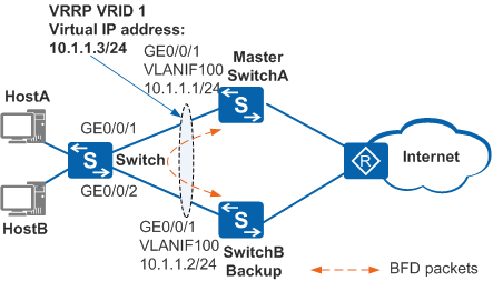
In Figure 1, hosts on a LAN are dual-homed to SwitchA and SwitchB through the switch. A VRRP group is established on SwitchA and SwitchB, and SwitchA is the master.
When SwitchA or a link between SwitchA and SwitchB is faulty, VRRP Advertisement packet negotiation takes a period of time. To implement a rapid active/standby switchover, deploy a BFD session on the link and associate the VRRP group with the BFD session. When the primary interface on the master or the link fails, the BFD session rapidly detects the fault and notifies the VRRP group of the fault. After receiving the notification, the VRRP group performs a rapid active/standby switchover. The backup becomes the Master and takes over traffic. This reduces the impact of the fault on service transmission.

In this scenario, to avoid loops, ensure that all connected interfaces have STP disabled and connected interfaces are removed from VLAN 1. If STP is enabled and VLANIF interfaces of switches are used to construct a Layer 3 ring network, an interface on the network will be blocked. As a result, Layer 3 services on the network cannot run normally.
Configuration Roadmap
The configuration roadmap is as follows:
- Assign an IP address to each interface and configure a routing protocol to ensure network connectivity.
- Configure a VRRP group on SwitchA and SwitchB. SwitchA functions as the master, its priority is 120, and the preemption delay is 20s. SwitchB functions as the backup and uses the default priority.
- Configure a static BFD session on SwitchA and SwitchB to monitor the link of the VRRP group.
- Configure association between VRRP and BFD on SwitchB to implement a rapid active/standby switchover if the link is faulty.
Procedure
- Configure devices to ensure network connectivity.
# Assign an IP address to each interface. SwitchA is used as an example. The configuration of SwitchB is similar to the configuration of SwitchA. For details, see the configuration files.
<HUAWEI> system-view
[HUAWEI] sysname SwitchA
[SwitchA] vlan 100
[SwitchA-vlan100] quit
[SwitchA] interface gigabitethernet 0/0/1
[SwitchA-GigabitEthernet0/0/1] port link-type hybrid
[SwitchA-GigabitEthernet0/0/1] port hybrid pvid vlan 100
[SwitchA-GigabitEthernet0/0/1] port hybrid untagged vlan 100
[SwitchA-GigabitEthernet0/0/1] quit
[SwitchA] interface vlanif 100
[SwitchA-Vlanif100] ip address 10.1.1.1 24
[SwitchA-Vlanif100] quit
# Configure Layer 2 transmission on the switch.
<HUAWEI> system-view
[HUAWEI] sysname Switch
[Switch] vlan 100
[Switch-vlan100] quit
[Switch] interface gigabitethernet 0/0/1
[Switch-GigabitEthernet0/0/1] port link-type hybrid
[Switch-GigabitEthernet0/0/1] port hybrid pvid vlan 100
[Switch-GigabitEthernet0/0/1] port hybrid untagged vlan 100
[Switch-GigabitEthernet0/0/1] quit
[Switch] interface gigabitethernet 0/0/2
[Switch-GigabitEthernet0/0/2] port link-type hybrid
[Switch-GigabitEthernet0/0/2] port hybrid pvid vlan 100
[Switch-GigabitEthernet0/0/2] port hybrid untagged vlan 100
[Switch-GigabitEthernet0/0/2] quit
# Configure OSPF between SwitchA and SwitchB. SwitchA is used as an example. The configuration of SwitchB is similar to the configuration of SwitchA, and is not mentioned here. For details, see the configuration files.
[SwitchA] ospf 1
[SwitchA-ospf-1] area 0
[SwitchA-ospf-1-area-0.0.0.0] network 10.1.1.0 0.0.0.255
[SwitchA-ospf-1-area-0.0.0.0] quit
[SwitchA-ospf-1] quit
- Configure a VRRP group.
# Configure VRRP group 1 on SwitchA, and set the priority of SwitchA to 120 and the preemption delay to 20s.
[SwitchA] interface vlanif 100
[SwitchA-Vlanif100] vrrp vrid 1 virtual-ip 10.1.1.3
[SwitchA-Vlanif100] vrrp vrid 1 priority 120
[SwitchA-Vlanif100] vrrp vrid 1 preempt-mode timer delay 20
[SwitchA-Vlanif100] quit
# Configure VRRP group 1 on SwitchB, and set the default priority of 100 for SwitchB.
[SwitchB] interface vlanif 100
[SwitchB-Vlanif100] vrrp vrid 1 virtual-ip 10.1.1.3
[SwitchB-Vlanif100] quit
- Configure a static BFD session.
# Create a BFD session on SwitchA.
[SwitchA] bfd
[SwitchA-bfd] quit
[SwitchA] bfd atob bind peer-ip 10.1.1.2 interface vlanif 100
[SwitchA-bfd-session-atob] discriminator local 1
[SwitchA-bfd-session-atob] discriminator remote 2
[SwitchA-bfd-session-atob] min-rx-interval 100
[SwitchA-bfd-session-atob] min-tx-interval 100
[SwitchA-bfd-session-atob] commit
[SwitchA-bfd-session-atob] quit
# Create a BFD session on SwitchB.
[SwitchB] bfd
[SwitchB-bfd] quit
[SwitchB] bfd btoa bind peer-ip 10.1.1.1 interface vlanif 100
[SwitchB-bfd-session-btoa] discriminator local 2
[SwitchB-bfd-session-btoa] discriminator remote 1
[SwitchB-bfd-session-btoa] min-rx-interval 100
[SwitchB-bfd-session-btoa] min-tx-interval 100
[SwitchB-bfd-session-btoa] commit
[SwitchB-bfd-session-btoa] quit
Run the display bfd session command on SwitchA and SwitchB. You can see that the BFD session is Up. The command output on SwitchA is used as an example.
[SwitchA] display bfd session all
--------------------------------------------------------------------------------
Local Remote PeerIpAddr      State     Type        InterfaceName
--------------------------------------------------------------------------------
1     2      10.1.1.2      Up        S_IP_IF     Vlanif100
--------------------------------------------------------------------------------
     Total UP/DOWN Session Number : 1/0
- Configure association between VRRP and BFD.
# Configure association between VRRP and BFD on SwitchB. When the BFD session goes Down, the priority of SwitchB increases by 40.
[SwitchB] interface vlanif 100
[SwitchB-Vlanif100] vrrp vrid 1 track bfd-session 2 increased 40
[SwitchB-Vlanif100] quit
- Verify the configuration.
# Run the display vrrp command on SwitchA and SwitchB. SwitchA is the master, SwitchB is the backup, and the associated BFD session is in Up state.
[SwitchA] display vrrp
  Vlanif100 | Virtual Router 1
    State : Master
    Virtual IP : 10.1.1.3
    Master IP : 10.1.1.1
    PriorityRun : 120
    PriorityConfig : 120
    MasterPriority : 120
    Preempt : YES   Delay Time : 20 s
    TimerRun : 1 s
    TimerConfig : 1 s
    Auth type : NONE
    Virtual MAC : 0000-5e00-0101
    Check TTL : YES
    Config type : normal-vrrp
    Backup-forward : disabled
    Create time : 2012-01-12 20:15:46
    Last change time : 2012-01-12 20:15:46
[SwitchB] display vrrp
  Vlanif100 | Virtual Router 1
    State : Backup
    Virtual IP : 10.1.1.3
    Master IP : 10.1.1.1
    PriorityRun : 100
    PriorityConfig : 100
    MasterPriority : 120
    Preempt : YES   Delay Time : 0 s
    TimerRun : 1 s
    TimerConfig : 1 s
    Auth type : NONE
    Virtual MAC : 0000-5e00-0101
    Check TTL : YES
    Config type : normal-vrrp
    Backup-forward : disabled
    Track BFD : 2  Priority increased : 40
    BFD-session state : UP
    Create time : 2012-01-12 20:15:46
    Last change time : 2012-01-12 20:15:46
# Run the shutdown command on GE0/0/1 of SwitchA to simulate a link fault. Then run the display vrrp command on SwitchA and SwitchB. You can see that SwitchA is in Initialize state, SwitchB assumes the master role, and the associated BFD session goes Down.
[SwitchA] interface gigabitethernet 0/0/1
[SwitchA-GigabitEthernet0/0/1] shutdown
[SwitchA-GigabitEthernet0/0/1] quit
[SwitchA] display vrrp
  Vlanif100 | Virtual Router 1
    State : Initialize
    Virtual IP : 10.1.1.3
    Master IP : 0.0.0.0
    PriorityRun : 120
    PriorityConfig : 120
    MasterPriority : 0
    Preempt : YES   Delay Time : 20 s
    TimerRun : 1 s
    TimerConfig : 1 s
    Auth type : NONE
    Virtual MAC : 0000-5e00-0101
    Check TTL : YES
    Config type : normal-vrrp
    Backup-forward : disabled
    Create time : 2012-01-12 20:15:46
    Last change time : 2012-01-12 20:15:46
[SwitchB] display vrrp
  Vlanif100 | Virtual Router 1
    State : Master
    Virtual IP : 10.1.1.3
    Master IP : 10.1.1.2
    PriorityRun : 140
    PriorityConfig : 100
    MasterPriority : 140
    Preempt : YES   Delay Time : 0 s
    TimerRun : 1 s
    TimerConfig : 1 s
    Auth type : NONE
    Virtual MAC : 0000-5e00-0101
    Check TTL : YES
    Config type : normal-vrrp
    Backup-forward : disabled
    Track BFD : 2  Priority increased : 40
    BFD-session state : DOWN
    Create time : 2012-01-12 20:15:46
    Last change time : 2012-01-12 20:15:46
# Run the undo shutdown command on GE0/0/1 of SwitchA.
[SwitchA] interface gigabitethernet 0/0/1
[SwitchA-GigabitEthernet0/0/1] undo shutdown
[SwitchA-GigabitEthernet0/0/1] quit
# After 20s, run the display vrrp command on SwitchA and SwitchB. You can see that SwitchA is the master, SwitchB is the backup, and the associated BFD session is in Up state.
[SwitchA] display vrrp
  Vlanif100 | Virtual Router 1
    State : Master
    Virtual IP : 10.1.1.3
    Master IP : 10.1.1.1
    PriorityRun : 120
    PriorityConfig : 120
    MasterPriority : 120
    Preempt : YES   Delay Time : 20 s
    TimerRun : 1 s
    TimerConfig : 1 s
    Auth type : NONE
    Virtual MAC : 0000-5e00-0101
    Check TTL : YES
    Config type : normal-vrrp
    Backup-forward : disabled
    Create time : 2012-01-12 20:15:46
    Last change time : 2012-01-12 20:15:46
[SwitchB] display vrrp
  Vlanif100 | Virtual Router 1
    State : Backup
    Virtual IP : 10.1.1.3
    Master IP : 10.1.1.1
    PriorityRun : 100
    PriorityConfig : 100
    MasterPriority : 120
    Preempt : YES   Delay Time : 0 s
    TimerRun : 1 s
    TimerConfig : 1 s
    Auth type : NONE
    Virtual MAC : 0000-5e00-0101
    Check TTL : YES
    Config type : normal-vrrp
    Backup-forward : disabled
    Track BFD : 2  Priority increased : 40
    BFD-session state : UP
    Create time : 2012-01-12 20:15:46
    Last change time : 2012-01-12 20:15:46
Configuration Files
SwitchA configuration file
#
sysname SwitchA
#
vlan batch 100
#
bfd
#
interface Vlanif100
 ip address 10.1.1.1 255.255.255.0
 vrrp vrid 1 virtual-ip 10.1.1.3
 vrrp vrid 1 priority 120
 vrrp vrid 1 preempt-mode timer delay 20
#
interface GigabitEthernet0/0/1
 port link-type hybrid
 port hybrid pvid vlan 100
 port hybrid untagged vlan 100
#
bfd atob bind peer-ip 10.1.1.2 interface Vlanif100
 discriminator local 1
 discriminator remote 2
 min-tx-interval 100
 min-rx-interval 100
 commit
#
ospf 1
 area 0.0.0.0
  network 10.1.1.0 0.0.0.255
#
return
SwitchB configuration file
#
sysname SwitchB
#
vlan batch 100
#
bfd
#
interface Vlanif100
 ip address 10.1.1.2 255.255.255.0
 vrrp vrid 1 virtual-ip 10.1.1.3
 vrrp vrid 1 track bfd-session 2 increased 40
#
interface GigabitEthernet0/0/1
 port link-type hybrid
 port hybrid pvid vlan 100
 port hybrid untagged vlan 100
#
bfd btoa bind peer-ip 10.1.1.1 interface Vlanif100
 discriminator local 2
 discriminator remote 1
 min-tx-interval 100
 min-rx-interval 100
 commit
#
ospf 1
 area 0.0.0.0
  network 10.1.1.0 0.0.0.255
#
return
Switch configuration file
#
sysname Switch
#
vlan batch 100
#
interface GigabitEthernet0/0/1
 port link-type hybrid
 port hybrid pvid vlan 100
 port hybrid untagged vlan 100
#
interface GigabitEthernet0/0/2
 port link-type hybrid
 port hybrid pvid vlan 100
 port hybrid untagged vlan 100
#
return