Example for Configuring VRRP on a Dot1q Termination Sub-interface
Networking Requirements

Only the S5720-EI, S5720-HI, S5730-HI, S5731-H, S5731-S, S5731S-H, S5731S-S, S5732-H, S6720-EI, S6720-HI, S6720S-EI, S6730-H, S6730S-H, S6730-S, and S6730S-S support this function.
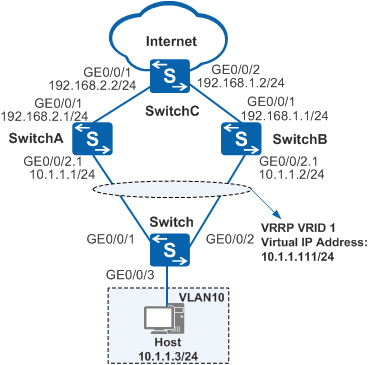
The host uses SwitchA as the default gateway to connect to the Internet. When SwitchA becomes faulty, SwitchB functions as the gateway. This implements gateway backup.
After SwitchA recovers, it becomes the gateway within 20s.
Configuration Roadmap
VRRP is configured on the Dot1q termination sub-interface to implement gateway redundancy. The configuration roadmap is as follows:
- Assign an IP address to each interface and configure a routing protocol to ensure network connectivity.
- Configure a VRRP group on sub-interfaces of SwitchA and SwitchB and set a higher priority for SwitchA so that SwitchA functions as the master to forward traffic. Then, set the preemption delay to 20s, and set a lower priority for SwitchB so that SwitchB functions as the backup.
VLAN termination sub-interfaces can be created on a non-VCMP client.
Procedure
- Configure devices to ensure network connectivity.
# Assign an IP address to each interface. SwitchA is used as an example. The configurations of SwitchB and SwitchC are similar to the configuration of SwitchA, and are not mentioned here. For details, see the configuration files.
<HUAWEI> system-view
[HUAWEI] sysname SwitchA
[SwitchA] interface gigabitethernet 0/0/2
[SwitchA-GigabitEthernet0/0/2] undo portswitch
[SwitchA-GigabitEthernet0/0/2] quit
[SwitchA] interface gigabitethernet 0/0/2.1
[SwitchA-GigabitEthernet0/0/2.1] ip address 10.1.1.1 24
[SwitchA-GigabitEthernet0/0/2.1] quit
[SwitchA] interface gigabitethernet 0/0/1
[SwitchA-GigabitEthernet0/0/1] undo portswitch
[SwitchA-GigabitEthernet0/0/1] ip address 192.168.2.1 24
[SwitchA-GigabitEthernet0/0/1] quit
# Configure Layer 2 forwarding on the switch.
<HUAWEI> system-view
[HUAWEI] sysname Switch
[Switch] vlan 10
[Switch-vlan10] quit
[Switch] interface gigabitethernet 0/0/1
[Switch-GigabitEthernet0/0/1] port link-type trunk
[Switch-GigabitEthernet0/0/1] port trunk allow-pass vlan 10
[Switch-GigabitEthernet0/0/1] quit
[Switch] interface gigabitethernet 0/0/2
[Switch-GigabitEthernet0/0/2] port link-type trunk
[Switch-GigabitEthernet0/0/2] port trunk allow-pass vlan 10
[Switch-GigabitEthernet0/0/2] quit
[Switch] interface gigabitethernet 0/0/3
[Switch-GigabitEthernet0/0/3] port link-type access
[Switch-GigabitEthernet0/0/3] port default vlan 10
[Switch-GigabitEthernet0/0/3] quit
# Configure OSPF between SwitchA, SwitchB, and SwitchC. SwitchA is used as an example. The configurations of SwitchB and SwitchC are similar to the configuration of SwitchA, and are not mentioned here. For details, see the configuration files.
[SwitchA] ospf 1
[SwitchA-ospf-1] area 0
[SwitchA-ospf-1-area-0.0.0.0] network 10.1.1.0 0.0.0.255
[SwitchA-ospf-1-area-0.0.0.0] network 192.168.2.0 0.0.0.255
[SwitchA-ospf-1-area-0.0.0.0] quit
[SwitchA-ospf-1] quit
- Configure VRRP on a Dot1q termination sub-interface.
# Configure VRRP group 1 on GE0/0/2.1 of SwitchA, and set the priority of SwitchA to 120 and the preemption delay to 20s.
[SwitchA] interface gigabitethernet 0/0/2.1
[SwitchA-GigabitEthernet0/0/2.1] dot1q termination vid 10
[SwitchA-GigabitEthernet0/0/2.1] arp broadcast enable
[SwitchA-GigabitEthernet0/0/2.1] vrrp vrid 1 virtual-ip 10.1.1.111
[SwitchA-GigabitEthernet0/0/2.1] vrrp vrid 1 priority 120
[SwitchA-GigabitEthernet0/0/2.1] vrrp vrid 1 preempt-mode timer delay 20
[SwitchA-GigabitEthernet0/0/2.1] quit
# Configure VRRP group 1 on GE0/0/2.1 of SwitchB, and set the default priority of 100 for SwitchB.
[SwitchB] interface gigabitethernet 0/0/2.1
[SwitchB-GigabitEthernet0/0/2.1] dot1q termination vid 10
[SwitchB-GigabitEthernet0/0/2.1] arp broadcast enable
[SwitchB-GigabitEthernet0/0/2.1] vrrp vrid 1 virtual-ip 10.1.1.111
[SwitchB-GigabitEthernet0/0/2.1] quit
- Verify the configuration.
# After the configuration is complete, run the display vrrp command on SwitchA and SwitchB. You can see that SwitchA is in Master state and SwitchB is in Backup state.
[SwitchA] display vrrp GigabitEthernet0/0/2.1 | Virtual Router 1 State : Master Virtual IP : 10.1.1.111 Master IP : 10.1.1.1 PriorityRun : 120 PriorityConfig : 120 MasterPriority : 120 Preempt : YES Delay Time : 20 s TimerRun : 1 s TimerConfig : 1 s Auth type : NONE Virtual MAC : 0000-5e00-0101 Check TTL : YES Config type : normal-vrrp Backup-forward : disabled Create time : 2012-05-30 21:25:47 Last change time : 2012-05-30 21:25:51[SwitchB] display vrrp GigabitEthernet0/0/2.1 | Virtual Router 1 State : Backup Virtual IP : 10.1.1.111 Master IP : 10.1.1.1 PriorityRun : 100 PriorityConfig : 100 MasterPriority : 120 Preempt : YES Delay Time : 0 s TimerRun : 1 s TimerConfig : 1 s Auth type : NONE Virtual MAC : 0000-5e00-0101 Check TTL : YES Config type : normal-vrrp Backup-forward : disabled Create time : 2012-05-30 21:25:47 Last change time : 2012-05-30 21:25:51# Run the display ip routing-table command on SwitchA and SwitchB. The command output shows that a direct route to the virtual IP address exists in the routing table of SwitchA and an OSPF route to the virtual IP address exists in the routing table of SwitchB.
[SwitchA] display ip routing-table Route Flags: R - relay, D - download to fib, T - to vpn-instance
------------------------------------------------------------------------------
Routing Tables: Public
         Destinations : 8       Routes : 9

Destination/Mask    Proto  Pre  Cost     Flags NextHop         Interface

       10.1.1.0/24  Direct 0    0          D   10.1.1.1        GigabitEthernet0/0/2.1
       10.1.1.1/32  Direct 0    0          D   127.0.0.1       GigabitEthernet0/0/2.1
   10.1.1.111/32  Direct 0   0          D   127.0.0.1      GigabitEthernet0/0/2.1
      127.0.0.0/8   Direct 0    0          D   127.0.0.1       InLoopBack0
      127.0.0.1/32  Direct 0    0          D   127.0.0.1       InLoopBack0
    192.168.1.0/24  OSPF   10   2          D   192.168.2.2     GigabitEthernet0/0/1
                    OSPF   10   2          D   10.1.1.2        GigabitEthernet0/0/2.1
    192.168.2.0/24  Direct 0    0          D   192.168.2.1     GigabitEthernet0/0/1
    192.168.2.1/32  Direct 0    0          D   127.0.0.1       GigabitEthernet0/0/1
[SwitchB] display ip routing-table Route Flags: R - relay, D - download to fib, T - to vpn-instance
------------------------------------------------------------------------------
Routing Tables: Public
         Destinations : 8       Routes : 9

Destination/Mask    Proto  Pre  Cost     Flags NextHop         Interface

       10.1.1.0/24  Direct 0    0          D  10.1.1.2         GigabitEthernet0/0/2.1
       10.1.1.2/32  Direct 0    0          D  127.0.0.1        GigabitEthernet0/0/2.1
   10.1.1.111/32  OSPF   10  2          D   10.1.1.1       GigabitEthernet0/0/2.1
      127.0.0.0/8   Direct 0    0          D  127.0.0.1        InLoopBack0
      127.0.0.1/32  Direct 0    0          D  127.0.0.1        InLoopBack0
    192.168.1.0/24  Direct 0    0          D  192.168.1.1      GigabitEthernet0/0/1
    192.168.1.1/32  Direct 0    0          D  127.0.0.1        GigabitEthernet0/0/1
    192.168.2.0/24  OSPF   10   2          D  192.168.1.2      GigabitEthernet0/0/1
                    OSPF   10   2          D  10.1.1.1         GigabitEthernet0/0/2.1
# Run the shutdown command on GE0/0/2.1 of SwitchA to simulate a link fault.
[SwitchA] interface gigabitethernet 0/0/2.1
[SwitchA-GigabitEthernet0/0/2.1] shutdown
[SwitchA-GigabitEthernet0/0/2.1] quit
# Run the display vrrp command on SwitchA and SwitchB. You can see that SwitchA is in Initialize state and SwitchB is in Master state.
[SwitchA] display vrrp GigabitEthernet0/0/2.1 | Virtual Router 1 State : Initialize Virtual IP : 10.1.1.111 Master IP : 0.0.0.0 PriorityRun : 120 PriorityConfig : 120 MasterPriority : 0 Preempt : YES Delay Time : 20 s TimerRun : 1 s TimerConfig : 1 s Auth type : NONE Virtual MAC : 0000-5e00-0101 Check TTL : YES Config type : normal-vrrp Backup-forward : disabled Create time : 2012-05-30 21:27:47 Last change time : 2012-05-30 21:27:51[SwitchB] display vrrp GigabitEthernet0/0/2.1 | Virtual Router 1 State : Master Virtual IP : 10.1.1.111 Master IP : 10.1.1.2 PriorityRun : 100 PriorityConfig : 100 MasterPriority : 100 Preempt : YES Delay Time : 0 s TimerRun : 1 s TimerConfig : 1 s Auth type : NONE Virtual MAC : 0000-5e00-0101 Check TTL : YES Config type : normal-vrrp Backup-forward : disabled Create time : 2012-05-30 21:27:47 Last change time : 2012-05-30 21:27:51# Run the undo shutdown command on GE0/0/2.1 of SwitchA.
[SwitchA] interface gigabitethernet 0/0/2.1
[SwitchA-GigabitEthernet0/0/2.1] undo shutdown
[SwitchA-GigabitEthernet0/0/2.1] quit
# After 20s, run the display vrrp command on SwitchA and SwitchB. You can see that SwitchA is in Master state and SwitchB is in Backup state.
[SwitchA] display vrrp GigabitEthernet0/0/2.1 | Virtual Router 1 State : Master Virtual IP : 10.1.1.111 Master IP : 10.1.1.1 PriorityRun : 120 PriorityConfig : 120 MasterPriority : 120 Preempt : YES Delay Time : 20 s TimerRun : 1 s TimerConfig : 1 s Auth type : NONE Virtual MAC : 0000-5e00-0101 Check TTL : YES Config type : normal-vrrp Backup-forward : disabled Create time : 2012-05-30 21:28:47 Last change time : 2012-05-30 21:28:51[SwitchB] display vrrp GigabitEthernet0/0/2.1 | Virtual Router 1 State : Backup Virtual IP : 10.1.1.111 Master IP : 10.1.1.1 PriorityRun : 100 PriorityConfig : 100 MasterPriority : 120 Preempt : YES Delay Time : 0 s TimerRun : 1 s TimerConfig : 1 s Auth type : NONE Virtual MAC : 0000-5e00-0101 Check TTL : YES Config type : normal-vrrp Backup-forward : disabled Create time : 2012-05-30 21:28:47 Last change time : 2012-05-30 21:28:51
Configuration Files
SwitchA configuration file
# sysname SwitchA # interface GigabitEthernet0/0/1 undo portswitch ip address 192.168.2.1 255.255.255.0 # interface GigabitEthernet0/0/2 undo portswitch # interface GigabitEthernet0/0/2.1 dot1q termination vid 10 ip address 10.1.1.1 255.255.255.0 vrrp vrid 1 virtual-ip 10.1.1.111 vrrp vrid 1 priority 120 vrrp vrid 1 preempt-mode timer delay 20 arp broadcast enable # ospf 1 area 0.0.0.0 network 10.1.1.0 0.0.0.255 network 192.168.2.0 0.0.0.255 # returnSwitchB configuration file
# sysname SwitchB # interface GigabitEthernet0/0/1 undo portswitch ip address 192.168.1.1 255.255.255.0 # interface GigabitEthernet0/0/2 undo portswitch # interface GigabitEthernet0/0/2.1 dot1q termination vid 10 ip address 10.1.1.2 255.255.255.0 vrrp vrid 1 virtual-ip 10.1.1.111 arp broadcast enable # ospf 1 area 0.0.0.0 network 10.1.1.0 0.0.0.255 network 192.168.1.0 0.0.0.255 # returnSwitchC configuration file
#
sysname SwitchC
#
interface GigabitEthernet0/0/1
 undo portswitch
 ip address 192.168.2.2 255.255.255.0
#
interface GigabitEthernet0/0/2
 undo portswitch
 ip address 192.168.1.2 255.255.255.0
#
ospf 1
 area 0.0.0.0
  network 192.168.1.0 0.0.0.255
  network 192.168.2.0 0.0.0.255
#
return
Switch configuration file
#
sysname Switch
#
vlan batch 10
#
interface GigabitEthernet0/0/1
 port link-type trunk
 port trunk allow-pass vlan 10
#
interface GigabitEthernet0/0/2
 port link-type trunk
 port trunk allow-pass vlan 10
#
interface GigabitEthernet0/0/3
 port link-type access
 port default vlan 10
#
return