Example for Configuring MSTP + VRRP Network
Networking Requirements
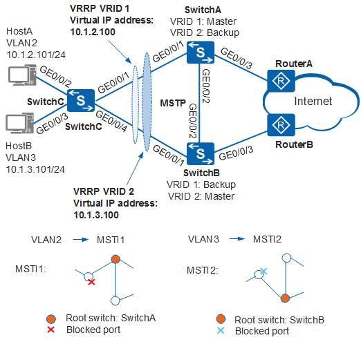
In Figure 1, hosts connect to SwitchC, and SwitchC connects to the Internet through SwitchA and SwitchB. To improve access reliability, the user configures redundant links. The redundant links cause a network loop, which leads to broadcast storms and MAC address damaging.
It is required that the network loop be prevented when redundant links are deployed, traffic be switched to another link when one link fails, and network bandwidth be effectively used.
MSTP can be configured on the network to prevent loops. MSTP blocks redundant links and prunes a network into a tree topology free from loops. In addition, VRRP needs to be configured on SwitchA and SwitchB. HostA connects to the Internet by using SwitchA as the default gateway and SwitchB as the backup gateway. HostB connects to the Internet by using SwitchB as the default gateway and SwitchA as the backup gateway. This loads balance traffic and improves communication reliability.
Device |
Interface |
VLANIF Interface |
IP Address |
|---|---|---|---|
SwitchA |
GE0/0/1 and GE0/0/2 |
VLANIF 2 |
10.1.2.102/24 |
GE0/0/1 and GE0/0/2 |
VLANIF 3 |
10.1.3.102/24 |
|
GE0/0/3 |
VLANIF 4 |
10.1.4.102/24 |
|
SwitchB |
GE0/0/1 and GE0/0/2 |
VLANIF 2 |
10.1.2.103/24 |
GE0/0/1 and GE0/0/2 |
VLANIF 3 |
10.1.3.103/24 |
|
GE0/0/3 |
VLANIF 5 |
10.1.5.103/24 |
Configuration Roadmap
The configuration roadmap is as follows:
Enable the protection function to protect devices or links. For example, enable the root protection function on the root bridge of each instance.
- Assign an IP address to each interface and configure a routing protocol on each device to ensure network connectivity.

SwitchA and SwitchB must support VRRP and OSPF. For details about models supporting VRRP and OSPF, see relevant documentation.
- Create VRRP group 1 and VRRP group 2 on SwitchA and SwitchB. Configure SwitchA as the master device and SwitchB as the backup device of VRRP group 1. Configure SwitchB as the master device and SwitchA as the backup device of VRRP group 2.
Procedure
- Configure basic MSTP functions.
Add SwitchA, SwitchB, and SwitchC to region RG1, and create instances MSTI 1 and MSTI 2.
# Configure an MST region on SwitchA.
<HUAWEI> system-view
[HUAWEI] sysname SwitchA
[SwitchA] stp region-configuration
[SwitchA-mst-region] region-name RG1
[SwitchA-mst-region] instance 1 vlan 2
[SwitchA-mst-region] instance 2 vlan 3
[SwitchA-mst-region] active region-configuration
[SwitchA-mst-region] quit
# Configure an MST region on SwitchB.
<HUAWEI> system-view
[HUAWEI] sysname SwitchB
[SwitchB] stp region-configuration
[SwitchB-mst-region] region-name RG1
[SwitchB-mst-region] instance 1 vlan 2
[SwitchB-mst-region] instance 2 vlan 3
[SwitchB-mst-region] active region-configuration
[SwitchB-mst-region] quit
# Configure an MST region on SwitchC.
<HUAWEI> system-view
[HUAWEI] sysname SwitchC
[SwitchC] stp region-configuration
[SwitchC-mst-region] region-name RG1
[SwitchC-mst-region] instance 1 vlan 2
[SwitchC-mst-region] instance 2 vlan 3
[SwitchC-mst-region] active region-configuration
[SwitchC-mst-region] quit
Configure the root bridge and secondary root bridge for MSTI 1 and MSTI 2 in RG1.
Configure the root bridge and secondary root bridge for MSTI 1.
# Set SwitchA as the root bridge of MSTI 1.
[SwitchA] stp instance 1 root primary
# Set SwitchB as the secondary root bridge of MSTI 1.
[SwitchB] stp instance 1 root secondary
Configure the root bridge and secondary root bridge for MSTI 2.
# Set SwitchB as the root bridge of MSTI 2.
[SwitchB] stp instance 2 root primary
# Set SwitchA as the secondary root bridge of MSTI 2.
[SwitchA] stp instance 2 root secondary
Set the path costs of the interfaces that you want to block in MSTI 1 and MSTI 2 to be greater than the default value.
# Set the path cost calculation method on SwitchA to Huawei calculation method.
[SwitchA] stp pathcost-standard legacy
# Set the path cost calculation method on SwitchB to Huawei calculation method.
[SwitchB] stp pathcost-standard legacy
# Set the path cost calculation method on SwitchC to Huawei calculation method. Set the path cost of GE0/0/1 in MSTI 2 to 20000, and set the path cost of GE0/0/4 in MSTI 1 to 20000.
[SwitchC] stp pathcost-standard legacy
[SwitchC] interface gigabitethernet 0/0/1
[SwitchC-GigabitEthernet0/0/1] stp instance 2 cost 20000
[SwitchC-GigabitEthernet0/0/1] quit
[SwitchC] interface gigabitethernet 0/0/4
[SwitchC-GigabitEthernet0/0/4] stp instance 1 cost 20000
[SwitchC-GigabitEthernet0/0/4] quit
-
-
# Enable MSTP on SwitchA.
[SwitchA] stp enable
# Enable MSTP on SwitchB.
[SwitchB] stp enable
# Enable MSTP on SwitchC.
[SwitchC] stp enable
Configure the ports connected to hosts as edge ports.
# Configure GE0/0/2 and GE0/0/3 of SwitchC as an edge port.
[SwitchC] interface gigabitethernet 0/0/2
[SwitchC-GigabitEthernet0/0/2] stp edged-port enable
[SwitchC-GigabitEthernet0/0/2] quit
[SwitchC] interface gigabitethernet 0/0/3
[SwitchC-GigabitEthernet0/0/3] stp edged-port enable
[SwitchC-GigabitEthernet0/0/3] quit
(Optional) Configure BPDU protection on SwitchC.
[SwitchC] stp bpdu-protection
Configure the ports connected to the router as edge ports.
# Configure GE0/0/3 of SwitchA as an edge port.
[SwitchA] interface gigabitethernet 0/0/3
[SwitchA-GigabitEthernet0/0/3] stp edged-port enable
[SwitchA-GigabitEthernet0/0/3] quit
(Optional) Configure BPDU protection on SwitchA.
[SwitchA] stp bpdu-protection
# Disable STP on GE0/0/3 of SwitchB as an edge port.
[SwitchB] interface gigabitethernet 0/0/3
[SwitchB-GigabitEthernet0/0/3] stp edged-port enable
[SwitchB-GigabitEthernet0/0/3] quit
(Optional) Configure BPDU protection on SwitchB.
[SwitchB] stp bpdu-protection
If edge ports are connected to network devices that have STP enabled and BPDU protection is enabled, the edge ports will be shut down and their attributes remain unchanged after they receive BPDUs.
-
- Enable the protection function on the designated interfaces of each root bridge.
# Enable root protection on GE0/0/1 of SwitchA.
[SwitchA] interface gigabitethernet 0/0/1
[SwitchA-GigabitEthernet0/0/1] stp root-protection
[SwitchA-GigabitEthernet0/0/1] quit
# Enable root protection on GE0/0/1 of SwitchB.
[SwitchB] interface gigabitethernet 0/0/1
[SwitchB-GigabitEthernet0/0/1] stp root-protection
[SwitchB-GigabitEthernet0/0/1] quit
- Configure Layer 2 forwarding on the switches in the ring.
Create VLANs 2 and 3 on SwitchA, SwitchB, and SwitchC.
# Create VLANs 2 and 3 on SwitchA.
[SwitchA] vlan batch 2 to 3
# Create VLANs 2 and 3 on SwitchB.
[SwitchB] vlan batch 2 to 3
# Create VLANs 2 and 3 on SwitchC.
[SwitchC] vlan batch 2 to 3
Add the interfaces connected to the ring network to VLANs.
# Add GE0/0/1 of SwitchA to VLANs.
[SwitchA] interface gigabitethernet 0/0/1
[SwitchA-GigabitEthernet0/0/1] port link-type trunk
[SwitchA-GigabitEthernet0/0/1] port trunk allow-pass vlan 2 to 3
[SwitchA-GigabitEthernet0/0/1] quit
# Add GE0/0/2 of SwitchA to VLANs.
[SwitchA] interface gigabitethernet 0/0/2
[SwitchA-GigabitEthernet0/0/2] port link-type trunk
[SwitchA-GigabitEthernet0/0/2] port trunk allow-pass vlan 2 to 3
[SwitchA-GigabitEthernet0/0/2] quit
# Add GE0/0/1 of SwitchB to VLANs.
[SwitchB] interface gigabitethernet 0/0/1
[SwitchB-GigabitEthernet0/0/1] port link-type trunk
[SwitchB-GigabitEthernet0/0/1] port trunk allow-pass vlan 2 to 3
[SwitchB-GigabitEthernet0/0/1] quit
# Add GE0/0/2 of SwitchB to VLANs.
[SwitchB] interface gigabitethernet 0/0/2
[SwitchB-GigabitEthernet0/0/2] port link-type trunk
[SwitchB-GigabitEthernet0/0/2] port trunk allow-pass vlan 2 to 3
[SwitchB-GigabitEthernet0/0/2] quit
# Add GE0/0/1 of SwitchC to VLANs.
[SwitchC] interface gigabitethernet 0/0/1
[SwitchC-GigabitEthernet0/0/1] port link-type trunk
[SwitchC-GigabitEthernet0/0/1] port trunk allow-pass vlan 2 to 3
[SwitchC-GigabitEthernet0/0/1] quit
# Add GE0/0/2 of SwitchC to VLAN 2.
[SwitchC] interface gigabitethernet 0/0/2
[SwitchC-GigabitEthernet0/0/2] port link-type access
[SwitchC-GigabitEthernet0/0/2] port default vlan 2
[SwitchC-GigabitEthernet0/0/2] quit
# Add GE0/0/3 of SwitchC to VLAN 3.
[SwitchC] interface gigabitethernet 0/0/3
[SwitchC-GigabitEthernet0/0/3] port link-type access
[SwitchC-GigabitEthernet0/0/3] port default vlan 3
[SwitchC-GigabitEthernet0/0/3] quit
# Add GE0/0/4 of SwitchC to VLANs.
[SwitchC] interface gigabitethernet 0/0/4
[SwitchC-GigabitEthernet0/0/4] port link-type trunk
[SwitchC-GigabitEthernet0/0/4] port trunk allow-pass vlan 2 to 3
[SwitchC-GigabitEthernet0/0/4] quit
- Verify the configuration.
After the preceding configurations are complete and the network topology becomes stable, perform the following operations to verify the configuration.
MSTI 1 and MSTI 2 are used as examples. You do not need to check the interface status in MSTI 0.
# Run the display stp brief command on SwitchA to view the status and protection mode on ports. Output similar to the following is displayed:
[SwitchA] display stp brief
 MSTID      Port                        Role  STP State       Protection
   0        GigabitEthernet0/0/1        DESI  FORWARDING      ROOT
   0        GigabitEthernet0/0/2        DESI  FORWARDING      NONE
   1        GigabitEthernet0/0/1        DESI  FORWARDING      ROOT
   1        GigabitEthernet0/0/2        DESI  FORWARDING      NONE
   2        GigabitEthernet0/0/1        DESI  FORWARDING      ROOT
   2        GigabitEthernet0/0/2        ROOT  FORWARDING      NONE
In MSTI 1, GE0/0/2 and GE0/0/1 of SwitchA are set as designated ports because SwitchA is the root bridge of MSTI 1. In MSTI 2, GE0/0/1 of SwitchA is set as the designated port and GE0/0/2 is set as the root port.
# Run the display stp brief command on SwitchB. Output similar to the following is displayed:
[SwitchB] display stp brief
 MSTID      Port                        Role  STP State       Protection
   0        GigabitEthernet0/0/1        DESI  FORWARDING      ROOT
   0        GigabitEthernet0/0/2        ROOT  FORWARDING      NONE
   1        GigabitEthernet0/0/1        DESI  FORWARDING      ROOT
   1        GigabitEthernet0/0/2        ROOT  FORWARDING      NONE
   2        GigabitEthernet0/0/1        DESI  FORWARDING      ROOT
   2        GigabitEthernet0/0/2        DESI  FORWARDING      NONE
In MSTI 2, GE0/0/1 and GE0/0/2 of SwitchB are set as designated ports because SwitchB is the root bridge of MSTI 2. In MSTI 1, GE0/0/1 of SwitchB is set as the designated port and GE0/0/2 is set as the root port.
# Run the display stp interface brief command on SwitchC. Output similar to the following is displayed:
[SwitchC] display stp interface gigabitethernet 0/0/1 brief
 MSTID      Port                        Role  STP State       Protection
   0        GigabitEthernet0/0/1        ROOT  FORWARDING      NONE
   1        GigabitEthernet0/0/1        ROOT  FORWARDING      NONE
   2        GigabitEthernet0/0/1        ALTE  DISCARDING      NONE
[SwitchC] display stp interface gigabitethernet 0/0/4 brief
 MSTID      Port                        Role  STP State       Protection
   0        GigabitEthernet0/0/4        ALTE  DISCARDING      NONE
   1        GigabitEthernet0/0/4        ALTE  DISCARDING      NONE
   2        GigabitEthernet0/0/4        ROOT  FORWARDING      NONE
GE0/0/1 of SwitchC is the root port of MSTI 1, and is blocked in MSTI 2. GE0/0/4 of SwitchC is the root port of MSTI 2, and is blocked in MSTI 1.
- Connect devices.
# Assign an IP address to each interface, for example, the interfaces on SwitchA. The configuration on SwitchB is similar to the configuration on SwitchA. For details, see the configuration files.
[SwitchA] vlan batch 4
[SwitchA] interface gigabitethernet 0/0/3
[SwitchA-GigabitEthernet0/0/3] port link-type trunk
[SwitchA-GigabitEthernet0/0/3] port trunk allow-pass vlan 4
[SwitchA-GigabitEthernet0/0/3] quit
[SwitchA] interface vlanif 2
[SwitchA-Vlanif2] ip address 10.1.2.102 24
[SwitchA-Vlanif2] quit
[SwitchA] interface vlanif 3
[SwitchA-Vlanif3] ip address 10.1.3.102 24
[SwitchA-Vlanif3] quit
[SwitchA] interface vlanif 4
[SwitchA-Vlanif4] ip address 10.1.4.102 24
[SwitchA-Vlanif4] quit
# Run OSPF on SwitchA, SwitchB, and routers. The configuration on SwitchA is used as an example. The configuration on SwitchB is similar to the configuration on SwitchA. For details, see the configuration files.
[SwitchA] ospf 1
[SwitchA-ospf-1] area 0
[SwitchA-ospf-1-area-0.0.0.0] network 10.1.2.0 0.0.0.255
[SwitchA-ospf-1-area-0.0.0.0] network 10.1.3.0 0.0.0.255
[SwitchA-ospf-1-area-0.0.0.0] network 10.1.4.0 0.0.0.255
[SwitchA-ospf-1-area-0.0.0.0] quit
[SwitchA-ospf-1] quit
- Configure VRRP groups.
# Create VRRP group 1 on SwitchA and SwitchB. Set SwitchA as the master device, priority to 120, and preemption delay to 20 seconds. Set SwitchB as the backup device and retain the default priority.
[SwitchA] interface vlanif 2
[SwitchA-Vlanif2] vrrp vrid 1 virtual-ip 10.1.2.100
[SwitchA-Vlanif2] vrrp vrid 1 priority 120
[SwitchA-Vlanif2] vrrp vrid 1 preempt-mode timer delay 20
[SwitchA-Vlanif2] quit
[SwitchB] interface vlanif 2
[SwitchB-Vlanif2] vrrp vrid 1 virtual-ip 10.1.2.100
[SwitchB-Vlanif2] quit
# Create VRRP group 2 on SwitchA and SwitchB. Set SwitchB as the master device, priority to 120, and preemption delay to 20 seconds. Set SwitchA as the backup device and retain the default priority.
[SwitchB] interface vlanif 3
[SwitchB-Vlanif3] vrrp vrid 2 virtual-ip 10.1.3.100
[SwitchB-Vlanif3] vrrp vrid 2 priority 120
[SwitchB-Vlanif3] vrrp vrid 2 preempt-mode timer delay 20
[SwitchB-Vlanif3] quit
[SwitchA] interface vlanif 3
[SwitchA-Vlanif3] vrrp vrid 2 virtual-ip 10.1.3.100
[SwitchA-Vlanif3] quit
# Set the virtual IP address 10.1.2.100 of VRRP group 1 as the default gateway of HostA, and the virtual IP address 10.1.3.100 of VRRP group 2 as the default gateway of HostB.
- Verify the configuration.
# Run the display vrrp command on SwitchA. SwitchA is the master in VRRP group 1 and backup in VRRP group 2.
[SwitchA] display vrrp
  Vlanif2 | Virtual Router 1
    State : Master
    Virtual IP : 10.1.2.100
    Master IP : 10.1.2.102
    PriorityRun : 120
    PriorityConfig : 120
    MasterPriority : 120
    Preempt : YES   Delay Time : 20 s
    TimerRun : 1 s
    TimerConfig : 1 s
    Auth type : NONE
    Virtual MAC : 0000-5e00-0101
    Check TTL : YES
    Config type : normal-vrrp
    Backup-forward : disabled
    Create time : 2012-05-11 11:39:18
    Last change time : 2012-05-26 11:38:58

  Vlanif3 | Virtual Router 2
    State : Backup
    Virtual IP : 10.1.3.100
    Master IP : 10.1.3.103
    PriorityRun : 100
    PriorityConfig : 100
    MasterPriority : 120
    Preempt : YES   Delay Time : 0 s
    TimerRun : 1 s
    TimerConfig : 1 s
    Auth type : NONE
    Virtual MAC : 0000-5e00-0102
    Check TTL : YES
    Config type : normal-vrrp
    Backup-forward : disabled
    Create time : 2012-05-11 11:40:18
    Last change time : 2012-05-26 11:48:58
# Run the display vrrp command on SwitchB. SwitchB is the backup in VRRP group 1 and master in VRRP group 2.
[SwitchB] display vrrp
  Vlanif2 | Virtual Router 1
    State : Backup
    Virtual IP : 10.1.2.100
    Master IP : 10.1.2.102
    PriorityRun : 100
    PriorityConfig : 100
    MasterPriority : 120
    Preempt : YES   Delay Time : 0 s
    TimerRun : 1 s
    TimerConfig : 1 s
    Auth type : NONE
    Virtual MAC : 0000-5e00-0101
    Check TTL : YES
    Config type : normal-vrrp
    Backup-forward : disabled
    Create time : 2012-05-11 11:39:18
    Last change time : 2012-05-26 11:38:58

  Vlanif3 | Virtual Router 2
    State : Master
    Virtual IP : 10.1.3.100
    Master IP : 10.1.3.103
    PriorityRun : 120
    PriorityConfig : 120
    MasterPriority : 120
    Preempt : YES   Delay Time : 20 s
    TimerRun : 1 s
    TimerConfig : 1 s
    Auth type : NONE
    Virtual MAC : 0000-5e00-0102
    Check TTL : YES
    Config type : normal-vrrp
    Backup-forward : disabled
    Create time : 2012-05-11 11:40:18
    Last change time : 2012-05-26 11:48:58
Configuration Files
-
#
sysname SwitchA
#
vlan batch 2 to 4
#
stp bpdu-protection
stp instance 1 root primary
stp instance 2 root secondary
stp pathcost-standard legacy
#
stp region-configuration
 region-name RG1
 instance 1 vlan 2
 instance 2 vlan 3
 active region-configuration
#
interface Vlanif2
 ip address 10.1.2.102 255.255.255.0
 vrrp vrid 1 virtual-ip 10.1.2.100
 vrrp vrid 1 priority 120
 vrrp vrid 1 preempt-mode timer delay 20
#
interface Vlanif3
 ip address 10.1.3.102 255.255.255.0
 vrrp vrid 2 virtual-ip 10.1.3.100
#
interface Vlanif4
 ip address 10.1.4.102 255.255.255.0
#
interface GigabitEthernet0/0/1
 port link-type trunk
 port trunk allow-pass vlan 2 to 3
 stp root-protection
#
interface GigabitEthernet0/0/2
 port link-type trunk
 port trunk allow-pass vlan 2 to 3
#
interface GigabitEthernet0/0/3
 port link-type trunk
 port trunk allow-pass vlan 4
 stp edged-port enable
#
ospf 1
 area 0.0.0.0
  network 10.1.2.0 0.0.0.255
  network 10.1.3.0 0.0.0.255
  network 10.1.4.0 0.0.0.255
#
return
-
#
sysname SwitchB
#
vlan batch 2 to 3 5
#
stp instance 1 root secondary
stp instance 2 root primary
stp bpdu-protection
stp pathcost-standard legacy
#
stp region-configuration
 region-name RG1
 instance 1 vlan 2
 instance 2 vlan 3
 active region-configuration
#
interface Vlanif2
 ip address 10.1.2.103 255.255.255.0
 vrrp vrid 1 virtual-ip 10.1.2.100
#
interface Vlanif3
 ip address 10.1.3.103 255.255.255.0
 vrrp vrid 2 virtual-ip 10.1.3.100
 vrrp vrid 2 priority 120
 vrrp vrid 2 preempt-mode timer delay 20
#
interface Vlanif5
 ip address 10.1.5.103 255.255.255.0
#
interface GigabitEthernet0/0/1
 port link-type trunk
 port trunk allow-pass vlan 2 to 3
 stp root-protection
#
interface GigabitEthernet0/0/2
 port link-type trunk
 port trunk allow-pass vlan 2 to 3
#
interface GigabitEthernet0/0/3
 port link-type trunk
 port trunk allow-pass vlan 5
 stp edged-port enable
#
ospf 1
 area 0.0.0.0
  network 10.1.2.0 0.0.0.255
  network 10.1.3.0 0.0.0.255
  network 10.1.5.0 0.0.0.255
#
return
-
#
sysname SwitchC
#
vlan batch 2 to 3
#
stp bpdu-protection
stp pathcost-standard legacy
#
stp region-configuration
 region-name RG1
 instance 1 vlan 2
 instance 2 vlan 3
 active region-configuration
#
interface GigabitEthernet0/0/1
 port link-type trunk
 port trunk allow-pass vlan 2 to 3
 stp instance 2 cost 20000
#
interface GigabitEthernet0/0/2
 port link-type access
 port default vlan 2
 stp edged-port enable
#
interface GigabitEthernet0/0/3
 port link-type access
 port default vlan 3
 stp edged-port enable
#
interface GigabitEthernet0/0/4
 port link-type trunk
 port trunk allow-pass vlan 2 to 3
 stp instance 1 cost 20000
#
return