Packet Identification
On a VXLAN network, VNIs are mapped to BDs in 1:1 mode. After a packet reaches a VTEP, the VTEP can identify the BD to which the packet belongs, then select a correct tunnel to forward the packet. Two methods are available for a VTEP to identify the VXLAN to which a packet belongs.
VXLAN Identification by VLAN
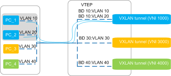
The 1:1 or N:1 mapping between VLANs and BDs is configured on VTEPs based on network planning. After a VTEP receives a service packet, it correctly selects a VXLAN tunnel to forward the packet based on the mapping between VLANs and BDs and the mapping between BDs and VNIs.
In Figure 1, VLAN 10 and VLAN 20 belong to BD 10. The mapping between VLANs 10 and 20 and BD 10, as well as the mapping between BD 10 and VNI 1000 are configured on the VTEP. After the VTEP receives a packet from PC_1 or PC_2, the VTEP forwards the packet over the VXLAN tunnel for VNI 1000.
VXLAN Identification by Encapsulation Mode
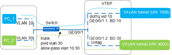
An encapsulation mode defines packet processing based on whether a packet contains VLAN tags. To implement VXLAN identification by encapsulation mode, Layer 2 sub-interfaces need to be configured on a downlink physical interface of a VTEP, and different encapsulation modes need to be configured for these sub-interfaces. The 1:1 mapping between Layer 2 sub-interfaces and BDs should also be defined. Then service packets are sent to specific Layer 2 sub-interfaces after reaching the VTEP. The VTEP selects a correct VXLAN tunnel to forward packets based on the mapping between Layer 2 sub-interfaces and BDs and the mapping between BDs and VNIs.
Table 1 lists four default packet processing methods of Layer 2 sub-interfaces that use different encapsulation modes.
Encapsulation Mode |
Allowed Packet Type |
Packet Encapsulation |
Packet Decapsulation |
|---|---|---|---|
dot1q |
With specified VLAN tag |
Removes the VLAN tag from original packets. |
Adds a VLAN tag to packets based on the VLAN ID for Dot1q termination on the sub-interface after VXLAN decapsulation and then forwards them. |
untag |
Without VLAN tags |
Does not perform any operation on the original packets. |
Does not perform any operation, including adding, replacing, or removing the VLAN tag, on packets after VXLAN decapsulation is implemented. |
default |
All packets regardless of whether they contain VLAN tags |
Does not perform any operation on the original packets. |
Does not perform any operation, including adding, replacing, or removing the VLAN tag, on packets after VXLAN decapsulation is implemented. |
qinq |
With specified double VLAN tags |
Removes all the VLAN tags from original packets. |
After implementing VXLAN decapsulation:
|
The encapsulation mode of the Layer 2 sub-interface GE0/0/1.1 is dot1q, allowing packets with VLAN tag 10 to enter the VXLAN tunnel.
The encapsulation mode of the Layer 2 sub-interface GE0/0/1.1 is untag, allowing packets without a VLAN tag to enter the VXLAN tunnel.
After packets from PC_1 or PC_2 reach the VTEP, the VTEP sends the packets to different Layer 2 sub-interfaces based VLAN tags in the packets. Then, the VTEP chooses a correct VXLAN tunnel to forward the packets based on the mapping between sub-interface and BD, as well as the mapping between BD and VNI.