Example for Configuring WLAN Services on a Large-Scale Network
Configuration Process
You need to configure and maintain WLAN features and functions in different profiles. These WLAN profiles include regulatory domain profile, radio profile, VAP profile, AP system profile, AP wired port profile, WIDS profile, WDS profile, and Mesh profile. When configuring WLAN services, you need to set related parameters in the WLAN profiles and bind the profiles to the AP group or APs. Then the configuration is automatically delivered to and takes effect on the APs. WLAN profiles can reference one another; therefore, you need to know the relationships among the profiles before configuring them. For details about the profile relationships and their basic configuration procedure, see WLAN Service Configuration Procedure.
Networking Requirements
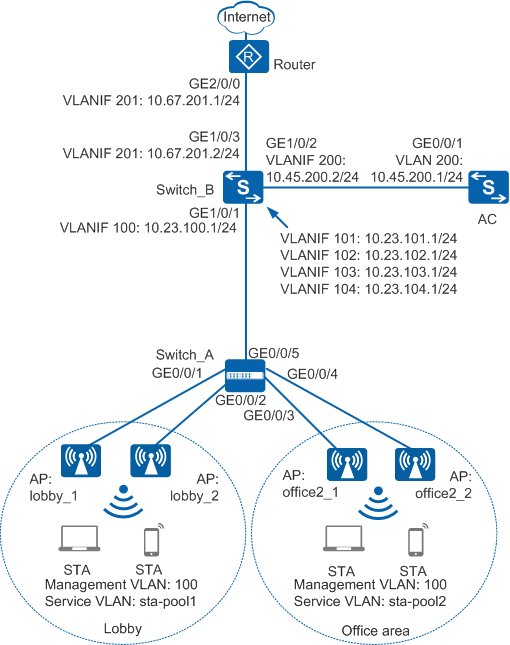
On a network of a large enterprise in Figure 1, an aggregation switch Switch_B connects to an access switch Switch_A and an upstream Router. The enterprise needs to deploy a WLAN, with as few changes to the current network structure as possible.
- A WLAN with the SSID guest is deployed in the lobby of the office building to provide wireless access services for visitors.
- A WLAN with the SSID employee is deployed in office areas to provide wireless access services for employees.
Configuration Roadmap
The configuration roadmap is as follows:
- Configure Switch_A and Switch_B to implement Layer 2 interconnection and configure Switch_B, Router, and AC to implement Layer 3 interconnection.
- Configure the Router as a DHCP server to assign IP addresses from a global address pool to STAs and APs.
- Configure a VLAN pool for service VLANs.
- Configure the APs to go online.
- Create an AP group and add APs that require the same configuration to the group for unified configuration.
- Configure AC system parameters, including the country code and source interface used by the AC to communicate with the APs.
- Configure the AP authentication mode and import the APs offline so that the APs can go online properly.
- Configure WLAN service parameters for STAs to access the WLAN.
Item |
Data |
|
|---|---|---|
DHCP server |
Router functions as a DHCP server to allocate IP addresses to the STAs and APs. |
|
IP address pool for the APs |
10.23.100.2-10.23.100.254/24 |
|
IP address pool for the STAs |
|
|
VLAN pool |
|
|
AC's source interface address |
VLANIF 200: 10.45.200.1/24 |
|
AP group |
Name: guest Referenced profile: VAP profile guest and regulatory domain profile domain1 |
|
Name: employee Referenced profile: VAP profile employee and regulatory domain profile domain1 |
||
Regulatory domain profile |
Name: domain1 Country code: CN |
|
SSID profile |
Name: guest SSID name: guest |
|
Name: employee SSID name: employee |
||
Security profile |
Name: guest
|
|
Name: employee
|
||
VAP profile |
Name: guest
|
|
Name: employee
|
||

For details about common WLAN configuration notes, see General Precautions for WLAN. For more deployment and configuration suggestions, see Wireless Network Deployment and Configuration Suggestions.
In this example, Switch_A is a Huawei fixed switch, and Switch_B is a Huawei modular switch.
When a VLAN pool is used to provide service VLANs on a large network, many VLANs are usually added to the VLAN pool, and interfaces of many devices need to be added to these VLANs. In this situation, quite a lot of broadcast domains are created if you configure the direct forwarding mode. To reduce the number of broadcast domains, set the data forwarding mode to direct forwarding.
- No ACK mechanism is provided for multicast packet transmission on air interfaces. In addition, wireless links are unstable. To ensure stable transmission of multicast packets, they are usually sent at low rates. If a large number of such multicast packets are sent from the network side, the air interfaces may be congested. You are advised to configure multicast packet suppression to reduce impact of a large number of low-rate multicast packets on the wireless network. Exercise caution when configuring the rate limit; otherwise, the multicast services may be affected.
- In direct forwarding mode, you are advised to configure multicast packet suppression on switch interfaces connected to APs.
- In tunnel forwarding mode, you are advised to configure multicast packet suppression in traffic profiles of the AC.
Configure port isolation on the interfaces of the device directly connected to APs. If port isolation is not configured and direct forwarding is used, a large number of unnecessary broadcast packets may be generated in the VLAN, blocking the network and degrading user experience.
In tunnel forwarding mode, the management VLAN and service VLAN cannot be the same. Only packets from the management VLAN are transmitted between the AC and APs. Packets from the service VLAN are not allowed between the AC and APs.
Procedure
- Set the NAC mode to unified on the AC so that users can connect to the network properly.
<HUAWEI> system-view
[HUAWEI] authentication unified-mode
If the NAC mode is changed from traditional to unified, the unified mode takes effect after you save the configuration and restart the device.
- Configure networking parameters.
# Configure access switch Switch_A. Add GE0/0/1 to GE0/0/5 to VLAN 100 (management VLAN), GE0/0/1 and GE0/0/2 to VLAN 101 and VLAN 102 (service VLANs), and GE0/0/3 and GE0/0/4 to VLAN 103 and VLAN 104 (service VLANs).
<HUAWEI> system-view
[HUAWEI] sysname Switch_A
[Switch_A] vlan batch 100
[Switch_A] interface gigabitethernet 0/0/1
[Switch_A-GigabitEthernet0/0/1] port link-type trunk
[Switch_A-GigabitEthernet0/0/1] port trunk pvid vlan 100
[Switch_A-GigabitEthernet0/0/1] port trunk allow-pass vlan 100 to 102
[Switch_A-GigabitEthernet0/0/1] port-isolate enable
[Switch_A-GigabitEthernet0/0/1] quit
[Switch_A] interface gigabitethernet 0/0/2
[Switch_A-GigabitEthernet0/0/2] port link-type trunk
[Switch_A-GigabitEthernet0/0/2] port trunk pvid vlan 100
[Switch_A-GigabitEthernet0/0/2] port trunk allow-pass vlan 100 to 102
[Switch_A-GigabitEthernet0/0/2] port-isolate enable
[Switch_A-GigabitEthernet0/0/2] quit
[Switch_A] interface gigabitethernet 0/0/3
[Switch_A-GigabitEthernet0/0/3] port link-type trunk
[Switch_A-GigabitEthernet0/0/3] port trunk pvid vlan 100
[Switch_A-GigabitEthernet0/0/3] port trunk allow-pass vlan 100 103 to 104
[Switch_A-GigabitEthernet0/0/3] port-isolate enable
[Switch_A-GigabitEthernet0/0/3] quit
[Switch_A] interface gigabitethernet 0/0/4
[Switch_A-GigabitEthernet0/0/4] port link-type trunk
[Switch_A-GigabitEthernet0/0/4] port trunk pvid vlan 100
[Switch_A-GigabitEthernet0/0/4] port trunk allow-pass vlan 100 103 to 104
[Switch_A-GigabitEthernet0/0/4] port-isolate enable
[Switch_A-GigabitEthernet0/0/4] quit
[Switch_A] interface gigabitethernet 0/0/5
[Switch_A-GigabitEthernet0/0/5] port link-type trunk
[Switch_A-GigabitEthernet0/0/5] port trunk allow-pass vlan 100 to 105
[Switch_A-GigabitEthernet0/0/5] quit
# Configure aggregation switch Switch_B. Add GE1/0/1 to VLAN 100 to VLAN 104, GE1/0/2 to VLAN 200, and GE1/0/3 to VLAN 201.
<HUAWEI> system-view
[HUAWEI] sysname Switch_B
[Switch_B] vlan batch 100 to 104 200 201
[Switch_B] interface gigabitethernet 1/0/1
[Switch_B-GigabitEthernet1/0/1] port link-type trunk
[Switch_B-GigabitEthernet1/0/1] port trunk allow-pass vlan 100 to 104
[Switch_B-GigabitEthernet1/0/1] quit
[Switch_B] interface gigabitethernet 1/0/2
[Switch_B-GigabitEthernet1/0/2] port link-type trunk
[Switch_B-GigabitEthernet1/0/2] port trunk allow-pass vlan 200
[Switch_B-GigabitEthernet1/0/2] quit
[Switch_B] interface gigabitethernet 1/0/3
[Switch_B-GigabitEthernet1/0/3] port link-type trunk
[Switch_B-GigabitEthernet1/0/3] port trunk allow-pass vlan 201
[Switch_B-GigabitEthernet1/0/3] quit
# Create VLANIF interfaces VLANIF 100 to VLANIF 104, VLANIF 200, and VLANIF 201 on Switch_B and configure their IP addresses. VLANIF 100 works as the gateway of APs. VLANIF 101 and VLANIF 102 work as the gateways of visitors while VLANIF 103 and VLANIF 104 work as the gateways of enterprise employees. Switch_B uses VLANIF 200 to communicate with the AC and VLANIF 201 to communicate with Router.
[Switch_B] interface vlanif 100
[Switch_B-Vlanif100] ip address 10.23.100.1 24
[Switch_B-Vlanif100] quit
[Switch_B] interface vlanif 101
[Switch_B-Vlanif101] ip address 10.23.101.1 24
[Switch_B-Vlanif101] quit
[Switch_B] interface vlanif 102
[Switch_B-Vlanif102] ip address 10.23.102.1 24
[Switch_B-Vlanif102] quit
[Switch_B] interface vlanif 103
[Switch_B-Vlanif103] ip address 10.23.103.1 24
[Switch_B-Vlanif103] quit
[Switch_B] interface vlanif 104
[Switch_B-Vlanif104] ip address 10.23.104.1 24
[Switch_B-Vlanif104] quit
[Switch_B] interface vlanif 200
[Switch_B-Vlanif200] ip address 10.45.200.2 24
[Switch_B-Vlanif200] quit
[Switch_B] interface vlanif 201
[Switch_B-Vlanif201] ip address 10.67.201.2 24
[Switch_B-Vlanif201] quit
# On the AC, add GE0/0/1 connected to Switch_B to VLAN 200.
<HUAWEI> system-view
[HUAWEI] sysname AC
[AC] vlan batch 101 to 104 200
[AC] interface vlanif 200
[AC-Vlanif200] ip address 10.45.200.1 24
[AC-Vlanif200] quit
[AC] interface gigabitethernet 0/0/1
[AC-GigabitEthernet0/0/1] port link-type trunk
[AC-GigabitEthernet0/0/1] port trunk allow-pass vlan 200
[AC-GigabitEthernet0/0/1] quit
# Add GE2/0/0 on Router to VLAN 201 and configure an IP address for VLANIF 201 so that Router can communicate with Switch_B.
<Huawei> system-view
[Huawei] sysname Router
[Router] vlan batch 201
[Router] interface vlanif 201
[Router-Vlanif201] ip address 10.67.201.1 24
[Router-Vlanif201] quit
[Router] interface gigabitethernet 2/0/0
[Router-GigabitEthernet2/0/0] port link-type trunk
[Router-GigabitEthernet2/0/0] port trunk allow-pass vlan 201
[Router-GigabitEthernet2/0/0] quit
# Configure routes from the Router to Switch_B.[Router] ip route-static 10.23.100.0 24 10.67.201.2 [Router] ip route-static 10.23.101.0 24 10.67.201.2 [Router] ip route-static 10.23.102.0 24 10.67.201.2 [Router] ip route-static 10.23.103.0 24 10.67.201.2 [Router] ip route-static 10.23.104.0 24 10.67.201.2
# Configure a default route on Switch_B with the outbound interface as the Router's VLANIF 201.
[Switch_B] ip route-static 0.0.0.0 0.0.0.0 10.67.201.1
# Configure a route on the AC with the next hop as Switch_B's VLANIF 200.[AC] ip route-static 10.23.100.0 24 10.45.200.2
- Configure a DHCP server to allocate IP addresses to APs and STAs.
# Configure Switch_B as a DHCP relay agent.
[Switch_B] dhcp enable
[Switch_B] interface vlanif 100
[Switch_B-Vlanif100] dhcp select relay
[Switch_B-Vlanif100] dhcp relay server-ip 10.67.201.1
[Switch_B-Vlanif100] quit
[Switch_B] interface vlanif 101
[Switch_B-Vlanif101] dhcp select relay
[Switch_B-Vlanif101] dhcp relay server-ip 10.67.201.1
[Switch_B-Vlanif101] quit
[Switch_B] interface vlanif 102
[Switch_B-Vlanif102] dhcp select relay
[Switch_B-Vlanif102] dhcp relay server-ip 10.67.201.1
[Switch_B-Vlanif102] quit
[Switch_B] interface vlanif 103
[Switch_B-Vlanif103] dhcp select relay
[Switch_B-Vlanif103] dhcp relay server-ip 10.67.201.1
[Switch_B-Vlanif103] quit
[Switch_B] interface vlanif 104
[Switch_B-Vlanif104] dhcp select relay
[Switch_B-Vlanif104] dhcp relay server-ip 10.67.201.1
[Switch_B-Vlanif104] quit
# Configure the Router as a DHCP server to allocate IP addresses to APs and STAs. If the AP and AC communicate through a Layer 3 network, configure Option 43 to notify the AP of the AC's IP address.
Configure the DNS server as required. The common methods are as follows:- In interface address pool scenarios, run the dhcp server dns-list ip-address &<1-8> command in the VLANIF interface view.
- In global address pool scenarios, run the dns-list ip-address &<1-8> command in the IP address pool view.
[Router] dhcp enable
[Router] ip pool ap
[Router-ip-pool-ap] network 10.23.100.0 mask 24
[Router-ip-pool-ap] gateway-list 10.23.100.1
[Router-ip-pool-ap] option 43 sub-option 3 ascii 10.45.200.1
[Router-ip-pool-ap] quit
[Router] ip pool sta1
[Router-ip-pool-sta1] network 10.23.101.0 mask 24
[Router-ip-pool-sta1] gateway-list 10.23.101.1
[Router-ip-pool-sta1] quit
[Router] ip pool sta2
[Router-ip-pool-sta2] network 10.23.102.0 mask 24
[Router-ip-pool-sta2] gateway-list 10.23.102.1
[Router-ip-pool-sta2] quit
[Router] ip pool sta3
[Router-ip-pool-sta3] network 10.23.103.0 mask 24
[Router-ip-pool-sta3] gateway-list 10.23.103.1
[Router-ip-pool-sta3] quit
[Router] ip pool sta4
[Router-ip-pool-sta4] network 10.23.104.0 mask 24
[Router-ip-pool-sta4] gateway-list 10.23.104.1
[Router-ip-pool-sta4] quit
[Router] interface vlanif 201
[Router-Vlanif201] dhcp select global
[Router-Vlanif201] quit
- Configure a VLAN pool for service VLANs.
# Create VLAN pools sta-pool1 and sta-pool2. Add VLAN 101 and VLAN 102 to VLAN pool sta-pool1, and VLAN 103 and VLAN 104 to VLAN pool sta-pool2. Set the VLAN assignment algorithm to hash for the two VLAN pools.
This example uses the VLAN assignment algorithm hash as an example. The default VLAN assignment algorithm is hash. If the default setting is not changed before, you do not need to run the assignment hash command.
In this example, only VLAN 101 and VLAN 102 are added to the VLAN pool. You can add multiple VLANs to a VLAN pool. Similar to adding VLAN 101 and VLAN 102 to a VLAN pool, you need to create corresponding VLANIF interfaces and configure IP addresses on Switch_B, and configure interface address pools on Router.
[AC] vlan pool sta-pool1
[AC-vlan-pool-sta-pool1] vlan 101 102
[AC-vlan-pool-sta-pool1] assignment hash
[AC-vlan-pool-sta-pool1] quit
[AC] vlan pool sta-pool2
[AC-vlan-pool-sta-pool2] vlan 103 104
[AC-vlan-pool-sta-pool2] assignment hash
[AC-vlan-pool-sta-pool2] quit
- Configure the APs to go online.
# Create AP groups guest and employee.
[AC] wlan
[AC-wlan-view] ap-group name guest
[AC-wlan-ap-group-guest] quit
[AC-wlan-view] ap-group name employee
[AC-wlan-ap-group-employee] quit
# Create a regulatory domain profile, configure the AC country code in the profile, and apply the profile to the AP groups.
[AC-wlan-view] regulatory-domain-profile name domain1
[AC-wlan-regulate-domain-domain1] country-code cn
[AC-wlan-regulate-domain-domain1] quit
[AC-wlan-view] ap-group name guest
[AC-wlan-ap-group-guest] regulatory-domain-profile domain1
Warning: Modifying the country code will clear channel, power and antenna gain configurations of the radio and reset the AP. Continue?[Y/N]:y
[AC-wlan-ap-group-guest] quit
[AC-wlan-view] ap-group name employee
[AC-wlan-ap-group-employee] regulatory-domain-profile domain1
Warning: Modifying the country code will clear channel, power and antenna gain configurations of the radio and reset the AP. Continue?[Y/N]:y
[AC-wlan-ap-group-employee] quit
[AC-wlan-view] quit
# Configure the AC's source interface.
[AC] capwap source interface vlanif 200
# Import the APs offline on the AC. Add APs deployed in the lobby to AP group guest and APs in office areas to AP group employee. Configure names for the APs based on the APs' deployment locations, so that you can know where the APs are deployed from their names. For example, if the AP with MAC address 60de-4474-9640 is deployed in room 1 of the second floor of the office building, name the AP office2-1. The default AP authentication mode is MAC address authentication. If the default settings are retained, you do not need to run the ap auth-mode mac-auth command.
In this example, the AP5030DN is used and has two radios: radio 0 (2.4 GHz radio) and radio 1 (5 GHz radio).
[AC] wlan
[AC-wlan-view] ap auth-mode mac-auth
[AC-wlan-view] ap-id 0 ap-mac 60de-4476-e360
[AC-wlan-ap-0] ap-name lobby-1
Warning: This operation may cause AP reset. Continue? [Y/N]:y
[AC-wlan-ap-0] ap-group guest
Warning: This operation may cause AP reset. If the country code changes, it will clear channel, power and antenna gain configuration s of the radio, Whether to continue? [Y/N]:y
[AC-wlan-ap-0] quit
[AC-wlan-view] ap-id 1 ap-mac 60de-4476-e380
[AC-wlan-ap-1] ap-name lobby-2
Warning: This operation may cause AP reset. Continue? [Y/N]:y
[AC-wlan-ap-1] ap-group guest
Warning: This operation may cause AP reset. If the country code changes, it will clear channel, power and antenna gain configuration s of the radio, Whether to continue? [Y/N]:y
[AC-wlan-ap-1] quit
[AC-wlan-view] ap-id 2 ap-mac 60de-4474-9640
[AC-wlan-ap-2] ap-name office2-1
Warning: This operation may cause AP reset. Continue? [Y/N]:y
[AC-wlan-ap-2] ap-group employee
Warning: This operation may cause AP reset. If the country code changes, it will clear channel, power and antenna gain configuration s of the radio, Whether to continue? [Y/N]:y
[AC-wlan-ap-2] quit
[AC-wlan-view] ap-id 3 ap-mac 60de-4474-9660
[AC-wlan-ap-3] ap-name office2-2
Warning: This operation may cause AP reset. Continue? [Y/N]:y
[AC-wlan-ap-3] ap-group employee
Warning: This operation may cause AP reset. If the country code changes, it will clear channel, power and antenna gain configuration s of the radio, Whether to continue? [Y/N]:y
[AC-wlan-ap-3] quit
# After the APs are powered on, run the display ap all command to check the AP state. If the State field is displayed as nor, the APs have gone online.
[AC-wlan-view] display ap all
Total AP information:
nor  : normal          [4]
Extrainfo : Extra information
P  : insufficient power supply
----------------------------------------------------------------------------------------------------
ID   MAC            Name      Group    IP            Type            State STA Uptime      ExtraInfo
----------------------------------------------------------------------------------------------------
0    60de-4474-9640 office2-1 employee 10.23.100.253 AP5030DN        nor   0   2H:30M:1S   -
1    60de-4474-9660 office2-2 employee 10.23.100.251 AP5030DN        nor   0   2H:35M:2S   -
2    60de-4476-e360 lobby-1   guest    10.23.100.254 AP5030DN        nor   0   2H:29M:29S   -
3    60de-4476-e380 lobby-2   guest    10.23.100.252 AP5030DN        nor   0   2H:34M:11S   -
----------------------------------------------------------------------------------------------------
Total: 4
- Configure WLAN service parameters.# Create security profiles guest and employee and configure the security policy in the profile.
In this example, the security policy is set to WPA2+PSK+AES and passwords to a1234567 and b1234567, respectively. In actual situations, the security policy must be configured according to service requirements.
[AC-wlan-view] security-profile name guest
[AC-wlan-sec-prof-guest] security wpa2 psk pass-phrase a1234567 aes
[AC-wlan-sec-prof-guest] quit
[AC-wlan-view] security-profile name employee
[AC-wlan-sec-prof-employee] security wpa2 psk pass-phrase b1234567 aes
[AC-wlan-sec-prof-employee] quit
# Create SSID profiles guest and employee, and set the SSID names to guest and employee, respectively.
[AC-wlan-view] ssid-profile name guest
[AC-wlan-ssid-prof-guest] ssid guest
[AC-wlan-ssid-prof-guest] quit
[AC-wlan-view] ssid-profile name employee
[AC-wlan-ssid-prof-employee] ssid employee
[AC-wlan-ssid-prof-employee] quit
# Create VAP profiles guest and employee, set the data forwarding mode and service VLANs, and apply the security profiles and SSID profiles to the VAP profiles.
[AC-wlan-view] vap-profile name guest
[AC-wlan-vap-prof-guest] forward-mode direct-forward
[AC-wlan-vap-prof-guest] service-vlan vlan-pool sta-pool1
[AC-wlan-vap-prof-guest] security-profile guest
[AC-wlan-vap-prof-guest] ssid-profile guest
[AC-wlan-vap-prof-guest] quit
[AC-wlan-view] vap-profile name employee
[AC-wlan-vap-prof-employee] forward-mode direct-forward
[AC-wlan-vap-prof-employee] service-vlan vlan-pool sta-pool2
[AC-wlan-vap-prof-employee] security-profile employee
[AC-wlan-vap-prof-employee] ssid-profile employee
[AC-wlan-vap-prof-employee] quit
# Bind VAP profiles to the AP groups and apply the VAP profiles to radio 0 and radio 1 of the APs.
[AC-wlan-view] ap-group name guest
[AC-wlan-ap-group-guest] vap-profile guest wlan 1 radio 0
[AC-wlan-ap-group-guest] vap-profile guest wlan 1 radio 1
[AC-wlan-ap-group-guest] quit
[AC-wlan-view] ap-group name employee
[AC-wlan-ap-group-employee] vap-profile employee wlan 1 radio 0
[AC-wlan-ap-group-employee] vap-profile employee wlan 1 radio 1
[AC-wlan-ap-group-employee] quit
- Set channels and power for the AP radios.
Automatic channel and power calibration functions are enabled by default. The manual channel and power configurations take effect only when these two functions are disabled. The channel and power configuration for the AP radios in this example is for reference only. In actual scenarios, configure channels and power for AP radios based on country codes of APs and network planning results.
# Disable automatic channel and power calibration functions of radio 0, and configure the channel and power for radio 0.[AC-wlan-view] ap-id 0 [AC-wlan-ap-0] radio 0 [AC-wlan-radio-0/0] calibrate auto-channel-select disable [AC-wlan-radio-0/0] calibrate auto-txpower-select disable [AC-wlan-radio-0/0] channel 20mhz 6 Warning: This action may cause service interruption. Continue?[Y/N]y [AC-wlan-radio-0/0] eirp 127 [AC-wlan-radio-0/0] quit# Disable automatic channel and power calibration functions of radio 1, and configure the channel and power for radio 1.[AC-wlan-ap-0] radio 1 [AC-wlan-radio-0/1] calibrate auto-channel-select disable [AC-wlan-radio-0/1] calibrate auto-txpower-select disable [AC-wlan-radio-0/1] channel 20mhz 149 Warning: This action may cause service interruption. Continue?[Y/N]y [AC-wlan-radio-0/1] eirp 127 [AC-wlan-radio-0/1] quit [AC-wlan-ap-0] quit - Verify the configuration.
After the service configuration is complete, run the display vap ssid guest and display vap ssid employee commands. If Status in the command output is displayed as ON, the VAPs have been successfully created on AP radios.
[AC-wlan-view] display vap ssid guest
WID : WLAN ID
--------------------------------------------------------------------------------
AP ID AP name RfID WID  BSSID          Status  Auth type     STA   SSID
--------------------------------------------------------------------------------
0     lobby-1 0    1   60DE-4476-E360  ON      WPA2-PSK      1     guest
0     lobby-1 1    1   60DE-4476-E370  ON      WPA2-PSK      0     guest
1     lobby-2 0    1   60DE-4476-E380  ON      WPA2-PSK      1     guest
1     lobby-2 1    1   60DE-4476-E390  ON      WPA2-PSK      0     guest
-------------------------------------------------------------------------------
Total: 4
[AC-wlan-view] display vap ssid employee
WID : WLAN ID
--------------------------------------------------------------------------------
AP ID AP name   RfID WID  SSID     BSSID          Status  Auth type     STA
--------------------------------------------------------------------------------
2     office2-1 0    1    employee 60DE-4474-9640 ON      WPA2-PSK      0
2     office2-1 1    1    employee 60DE-4474-9650 ON      WPA2-PSK      1
3     office2-2 0    1    employee 60DE-4474-9660 ON      WPA2-PSK      0
3     office2-2 1    1    employee 60DE-4474-9670 ON      WPA2-PSK      1
-------------------------------------------------------------------------------
Total: 4
Connect STAs to the WLANs with SSIDs guest and employee and enter the passwords a1234567 and b1234567 respectively. Run the display station ssid guest and display station ssid employee commands on the AC. The command output shows that the STAs are connected to the WLANs guest and employee.
[AC-wlan-view] display station ssid guest
Rf/WLAN: Radio ID/WLAN ID
Rx/Tx: link receive rate/link transmit rate(Mbps)
------------------------------------------------------------------------------
STA MAC         AP ID Ap name    Rf/WLAN  Band  Type  Rx/Tx      RSSI  VLAN  IP address
------------------------------------------------------------------------------
581f-28fc-7ead  0     lobby-1    0/1      2.4G  11n   2/4        -53   101   10.23.101.254
------------------------------------------------------------------------------
Total: 1 2.4G: 1 5G: 0
[AC-wlan-view] display station ssid employee
Rf/WLAN: Radio ID/WLAN ID
Rx/Tx: link receive rate/link transmit rate(Mbps)
------------------------------------------------------------------------------
STA MAC         AP ID Ap name      Rf/WLAN  Band  Type  Rx/Tx      RSSI  VLAN  IP address
------------------------------------------------------------------------------
e019-1dc7-1e08  2     office2-1    1/1      5G    11n   26/51      -61   103   10.23.103.254
------------------------------------------------------------------------------
Total: 1 2.4G: 0 5G: 1
Configuration Files
Switch_A configuration file
#
sysname Switch_A
#
vlan batch 100
#
interface GigabitEthernet0/0/1
 port link-type trunk
 port trunk pvid vlan 100
 port trunk allow-pass vlan 100 to 102
 port-isolate enable group 1
#
interface GigabitEthernet0/0/2
 port link-type trunk
 port trunk pvid vlan 100
 port trunk allow-pass vlan 100 to 102
 port-isolate enable group 1
#
interface GigabitEthernet0/0/3
 port link-type trunk
 port trunk pvid vlan 100
 port trunk allow-pass vlan 100 103 to 104
 port-isolate enable group 1
#
interface GigabitEthernet0/0/4
 port link-type trunk
 port trunk pvid vlan 100
 port trunk allow-pass vlan 100 103 to 104
 port-isolate enable group 1
#
interface GigabitEthernet0/0/5
 port link-type trunk
 port trunk allow-pass vlan 100 to 104
#
return
Switch_B configuration file
#
sysname Switch_B
#
vlan batch 100 to 104 200 201
#
dhcp enable
#
interface Vlanif100
 ip address 10.23.100.1 255.255.255.0
 dhcp select relay
 dhcp relay server-ip 10.67.201.1
#
interface Vlanif101
 ip address 10.23.101.1 255.255.255.0
 dhcp select relay
 dhcp relay server-ip 10.67.201.1
#
interface Vlanif102
 ip address 10.23.102.1 255.255.255.0
 dhcp select relay
 dhcp relay server-ip 10.67.201.1
#
interface Vlanif103
 ip address 10.23.103.1 255.255.255.0
 dhcp select relay
 dhcp relay server-ip 10.67.201.1
#
interface Vlanif104
 ip address 10.23.104.1 255.255.255.0
 dhcp select relay
 dhcp relay server-ip 10.67.201.1
#
interface Vlanif200
 ip address 10.45.200.2 255.255.255.0
#
interface Vlanif201
 ip address 10.67.201.2 255.255.255.0
#
interface GigabitEthernet1/0/1
 port link-type trunk
 port trunk allow-pass vlan 100 to 104
#
interface GigabitEthernet1/0/2
 port link-type trunk
 port trunk allow-pass vlan 200
#
interface GigabitEthernet1/0/3
 port link-type trunk
 port trunk allow-pass vlan 201
#
ip route-static 0.0.0.0 0.0.0.0 10.67.201.1
#
return
Router configuration file
#
sysname Router
#
vlan batch 201
#
dhcp enable
#
ip pool ap
 gateway-list 10.23.100.1
 network 10.23.100.0 mask 255.255.255.0
 option 43 sub-option 3 ascii 10.45.200.1
#
ip pool sta1
 gateway-list 10.23.101.1
 network 10.23.101.0 mask 255.255.255.0
#
ip pool sta2
 gateway-list 10.23.102.1
 network 10.23.102.0 mask 255.255.255.0
#
ip pool sta3
 gateway-list 10.23.103.1
 network 10.23.103.0 mask 255.255.255.0
#
ip pool sta4
 gateway-list 10.23.104.1
 network 10.23.104.0 mask 255.255.255.0
#
interface Vlanif201
 ip address 10.67.201.1 255.255.255.0
 dhcp select global
#
interface GigabitEthernet2/0/0
 port link-type trunk
 port trunk allow-pass vlan 201
#
ip route-static 10.23.100.0 255.255.255.0 10.67.201.2
ip route-static 10.23.101.0 255.255.255.0 10.67.201.2
ip route-static 10.23.102.0 255.255.255.0 10.67.201.2
ip route-static 10.23.103.0 255.255.255.0 10.67.201.2
ip route-static 10.23.104.0 255.255.255.0 10.67.201.2
#
return
AC configuration file
#
 sysname AC
#
vlan batch 101 to 104 200
#
vlan pool sta-pool1
 vlan 101 to 102
vlan pool sta-pool2
 vlan 103 to 104
#
interface Vlanif200
 ip address 10.45.200.1 255.255.255.0
#
interface GigabitEthernet0/0/1
 port link-type trunk
 port trunk allow-pass vlan 101 to 104 200
#
ip route-static 10.23.100.0 255.255.255.0 10.45.200.2
#
capwap source interface vlanif200
#
wlan
 security-profile name guest
  security wpa2 psk pass-phrase %^%#m"tz0f>~7.[`^6RWdzwCy16hJj/Mc!,}s`X*B]}A%^%# aes
 security-profile name employee
  security wpa2 psk pass-phrase %^%#H{1<-b]4~"*+Y:4-'/URy;$+,33UgQf)@9I(Yl]V%^%# aes
 ssid-profile name guest
  ssid guest
 ssid-profile name employee
  ssid employee
 vap-profile name guest
  service-vlan vlan-pool sta-pool1
  ssid-profile guest
  security-profile guest
 vap-profile name employee
  service-vlan vlan-pool sta-pool2
  ssid-profile employee
  security-profile employee
 regulatory-domain-profile name domain1
 ap-group name guest
  regulatory-domain-profile domain1
  radio 0
   vap-profile guest wlan 1
  radio 1
   vap-profile guest wlan 1
 ap-group name employee
  regulatory-domain-profile domain1
  radio 0
   vap-profile employee wlan 1
  radio 1
   vap-profile employee wlan 1
 ap-id 0 type-id 35 ap-mac 60de-4476-e360 ap-sn 210235554710CB000042
  ap-name lobby-1
  ap-group guest
  radio 0
   channel 20mhz 6
   eirp 127
   calibrate auto-channel-select disable
   calibrate auto-txpower-select disable
  radio 1
   channel 20mhz 149
   eirp 127
   calibrate auto-channel-select disable
   calibrate auto-txpower-select disable
 ap-id 1 type-id 35 ap-mac 60de-4476-e380 ap-sn 210235419610D2000066
  ap-name lobby-2
  ap-group guest
 ap-id 2 type-id 35 ap-mac 60de-4474-9640 ap-sn 210235554710CB000075
  ap-name office2-1
  ap-group employee
 ap-id 3 type-id 35 ap-mac 60de-4474-9660 ap-sn 210235419610D2000097
  ap-name office2-2
  ap-group employee
#
return