Example for Configuring Seamless Channel Switching
Configuration Process
You need to configure and maintain WLAN features and functions in different profiles. These WLAN profiles include regulatory domain profile, radio profile, VAP profile, AP system profile, AP wired port profile, WIDS profile, WDS profile, and Mesh profile. When configuring WLAN services, you need to set related parameters in the WLAN profiles and bind the profiles to the AP group or APs. Then the configuration is automatically delivered to and takes effect on the APs. WLAN profiles can reference one another; therefore, you need to know the relationships among the profiles before configuring them. For details about the profile relationships and their basic configuration procedure, see WLAN Service Configuration Procedure.
Networking Requirements
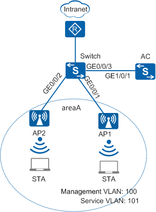
An enterprise deploys WLAN area A to provide WLAN services. As shown in Figure 1, AP1 and AP2 are directly connected to the switch, service data is directly forwarded in AC bypass deployment mode, and the switch connects to the Internet through the egress route. The enterprise requires that WLAN services not be interrupted even when the APs change their working channels.
Configuration Roadmap
- Configure basic WLAN services.
- Configure seamless channel switching to improve WLAN service reliability so that services are not interrupted even when APs change their working channels.
Item |
Data |
|---|---|
DHCP server |
Switch, which assigns IP addresses to STAs and APs |
IP address pool for APs |
10.1.1.3-10.1.1.254/24 |
IP address pool for STAs |
10.1.2.2-10.1.2.254/24 |
Gateway address for APs |
10.1.1.1/24 |
Gateway address for STAs |
10.1.2.1/24 |
AC source interface |
VLANIF100: 10.1.1.2/24 |
AP group |
|
Regulatory domain profile |
|
SSID profile |
|
Security profile |
|
VAP profile |
|
2G radio profile |
|
Configuration Notes
For details about common WLAN configuration notes, see General Precautions for WLAN. For more deployment and configuration suggestions, see Wireless Network Deployment and Configuration Suggestions.
- No ACK mechanism is provided for multicast packet transmission on air interfaces. In addition, wireless links are unstable. To ensure stable transmission of multicast packets, they are usually sent at low rates. If a large number of such multicast packets are sent from the network side, the air interfaces may be congested. You are advised to configure multicast packet suppression to reduce impact of a large number of low-rate multicast packets on the wireless network. Exercise caution when configuring the rate limit; otherwise, the multicast services may be affected.
- In direct forwarding mode, you are advised to configure multicast packet suppression on switch interfaces connected to APs.
- In tunnel forwarding mode, you are advised to configure multicast packet suppression in traffic profiles of the AC.
Configure port isolation on the interfaces of the device directly connected to APs. If port isolation is not configured and direct forwarding is used, a large number of unnecessary broadcast packets may be generated in the VLAN, blocking the network and degrading user experience.
In tunnel forwarding mode, the management VLAN and service VLAN cannot be the same. Only packets from the management VLAN are transmitted between the AC and APs. Packets from the service VLAN are not allowed between the AC and APs.
Procedure
- Set the NAC mode to unified on the AC so that users can connect to the network properly.
<HUAWEI> system-view
[HUAWEI] authentication unified-mode

If the NAC mode is changed from traditional to unified, the unified mode takes effect after you save the configuration and restart the device.
- Configure the switch and AC to enable the AC to communicate with the APs.
# Create VLAN100 (management VLAN) and VLAN101 (service VLAN) on the switch. Set the link type of GE0/0/1 that connects the switch to AP1 and GE0/0/2 that connects the switch to AP2 to trunk and PVID of the interfaces to 100, and configure the interfaces to allow packets of VLAN100 and VLAN101 to pass. Set the link type of GE0/0/3 on the switch to trunk, and configure the interface to allow packets of VLAN100 to pass.
<HUAWEI> system-view
[HUAWEI] sysname Switch
[Switch] vlan batch 100 101
[Switch] interface gigabitethernet 0/0/1
[Switch-GigabitEthernet0/0/1] port link-type trunk
[Switch-GigabitEthernet0/0/1] port trunk pvid vlan 100
[Switch-GigabitEthernet0/0/1] port trunk allow-pass vlan 100 to 101
[Switch-GigabitEthernet0/0/1] port-isolate enable
[Switch-GigabitEthernet0/0/1] quit
[Switch] interface gigabitethernet 0/0/2
[Switch-GigabitEthernet0/0/2] port link-type trunk
[Switch-GigabitEthernet0/0/2] port trunk pvid vlan 100
[Switch-GigabitEthernet0/0/2] port trunk allow-pass vlan 100 to 101
[Switch-GigabitEthernet0/0/2] port-isolate enable
[Switch-GigabitEthernet0/0/2] quit
[Switch] interface gigabitethernet 0/0/3
[Switch-GigabitEthernet0/0/3] port link-type trunk
[Switch-GigabitEthernet0/0/3] port trunk allow-pass vlan 100
[Switch-GigabitEthernet0/0/3] quit
# Add GE0/0/1 that connects the AC to the switch to VLAN100.
<HUAWEI> system-view
[HUAWEI] sysname AC
[AC] vlan batch 100 101
[AC] interface gigabitethernet 0/0/1
[AC-GigabitEthernet0/0/1] port link-type trunk
[AC-GigabitEthernet0/0/1] port trunk allow-pass vlan 100
[AC-GigabitEthernet0/0/1] quit
- Configure the DHCP function on the switch to allocate IP addresses to APs and STAs.
# Configure VLANIF100 to use the interface address pool to allocate IP addresses to APs.
[Switch] dhcp enable
[Switch] interface vlanif 100
[Switch-Vlanif100] ip address 10.1.1.1 255.255.255.0
[Switch-Vlanif100] dhcp select interface
[Switch-Vlanif100] dhcp server excluded-ip-address 10.1.1.2
[Switch-Vlanif100] quit
# Configure VLANIF101 to use the interface address pool to allocate IP addresses to STAs.
Configure the DNS server as required. The common methods are as follows:- In interface address pool scenarios, run the dhcp server dns-list ip-address &<1-8> command in the VLANIF interface view.
- In global address pool scenarios, run the dns-list ip-address &<1-8> command in the IP address pool view.
[Switch] interface vlanif 101
[Switch-Vlanif101] ip address 10.1.2.1 255.255.255.0
[Switch-Vlanif101] dhcp select interface
[Switch-Vlanif101] quit
- Configure the APs to go online.
# Create an AP group and add the APs to the AP group.
[AC] wlan
[AC-wlan-view] ap-group name ap-group1
[AC-wlan-ap-group-ap-group1] quit
# Create a regulatory domain profile, configure the AC country code in the profile, and apply the profile to the AP group.
[AC-wlan-view] regulatory-domain-profile name domain
[AC-wlan-regulate-domain-domain] country-code cn
[AC-wlan-regulate-domain-domain] quit
[AC-wlan-view] ap-group name ap-group1
[AC-wlan-ap-group-ap-group1] regulatory-domain-profile domain
Warning: Modifying the country code will clear channel, power and antenna gain configurations of the radio and reset the AP. Continue?[Y/N]:y
[AC-wlan-ap-group-ap-group1] quit
[AC-wlan-view] quit
# Configure the AC's source interface.
[AC] interface vlanif 100
[AC-Vlanif100] ip address 10.1.1.2 255.255.255.0
[AC-Vlanif100] quit
[AC] capwap source interface vlanif 100
# Import the APs offline on the AC and add AP1 and AP2 to the AP group ap-group1. In this example, the MAC addresses of AP1 and AP2 are 60de-4476-e360 and dcd2-fc04-b500, respectively. Configure names for the APs based on the APs' deployment locations, so that you can know where the APs are located. For example, if AP1 with MAC address 60de-4476-e360 is deployed in area 1, name AP1 area_1. The default AP authentication mode is MAC address authentication. If the default settings are retained, you do not need to run the ap auth-mode mac-auth command.
In this example, the AP5030DN is used and has two radios: radio 0 (2.4 GHz radio) and radio 1 (5 GHz radio).
[AC] wlan
[AC-wlan-view] ap auth-mode mac-auth
[AC-wlan-view] ap-id 0 ap-mac 60de-4476-e360
[AC-wlan-ap-0] ap-name area_1
Warning: This operation may cause AP reset. Continue? [Y/N]:y
[AC-wlan-ap-0] ap-group ap-group1
Warning: This operation may cause AP reset. If the country code changes, it will clear channel, power and antenna gain configuration s of the radio, Whether to continue? [Y/N]:y
[AC-wlan-ap-0] quit
[AC-wlan-view] ap-id 1 ap-mac dcd2-fc04-b500
[AC-wlan-ap-1] ap-name area_2
Warning: This operation may cause AP reset. Continue? [Y/N]:y
[AC-wlan-ap-1] ap-group ap-group1
Warning: This operation may cause AP reset. If the country code changes, it will clear channel, power and antenna gain configuration s of the radio, Whether to continue? [Y/N]:y
[AC-wlan-ap-1] quit
# After the AP is powered on, run the display ap all command to check the AP state. If the State field is displayed as nor, the AP goes online normally.
[AC-wlan-view] display ap all
Total AP information:
nor  : normal          [2]
Extrainfo : Extra information
P  : insufficient power supply
--------------------------------------------------------------------------------------------------
ID   MAC            Name   Group     IP            Type            State STA Uptime      ExtraInfo
--------------------------------------------------------------------------------------------------
0    60de-4476-e360 area_1 ap-group1 10.1.1.253    AP5030DN        nor   0   10S    -
1    dcd2-fc04-b500 area_2 ap-group1 10.1.1.254    AP5030DN        nor   0   10S    -
--------------------------------------------------------------------------------------------------
Total: 2
- Configure WLAN service parameters.# Create security profile wlan-security and set the security policy in the profile.
In this example, the security policy is set to WPA2+PSK+AES and password to a1234567. In actual situations, the security policy must be configured according to service requirements.
[AC-wlan-view] security-profile name wlan-security
[AC-wlan-sec-prof-wlan-security] security wpa2 psk pass-phrase a1234567 aes
[AC-wlan-sec-prof-wlan-security] quit
# Create SSID profile wlan-ssid and set the SSID name to wlan-net.
[AC-wlan-view] ssid-profile name wlan-ssid
[AC-wlan-ssid-prof-wlan-ssid] ssid wlan-net
[AC-wlan-ssid-prof-wlan-ssid] quit
# Create the 2G radio profile wlan-radio2g and the 5G radio profile wlan-radio5g, and configure the seamless channel switching function.
The following example configures a 2G radio profile. The configuration of a 5G radio profile is similar.
[AC-wlan-view] radio-2g-profile name wlan-radio2g
[AC-wlan-radio-2g-prof-wlan-radio2g] undo channel-switch announcement disable
[AC-wlan-radio-2g-prof-wlan-radio2g] channel-switch mode continue-transmitting
[AC-wlan-radio-2g-prof-wlan-radio2g] quit
[AC-wlan-view] radio-5g-profile name wlan-radio5g
[AC-wlan-radio-5g-prof-wlan-radio5g] undo channel-switch announcement disable
[AC-wlan-radio-5g-prof-wlan-radio5g] channel-switch mode continue-transmitting
[AC-wlan-radio-5g-prof-wlan-radio5g] quit
# Create VAP profile wlan-vap, set the data forwarding mode and service VLAN, and apply the security profile and SSID profile to the VAP profile.
[AC-wlan-view] vap-profile name wlan-vap
[AC-wlan-vap-prof-wlan-vap] forward-mode direct-forward
[AC-wlan-vap-prof-wlan-vap] service-vlan vlan-id 101
[AC-wlan-vap-prof-wlan-vap] security-profile wlan-security
[AC-wlan-vap-prof-wlan-vap] ssid-profile wlan-ssid
[AC-wlan-vap-prof-wlan-vap] quit
# Bind the 2G radio profile, 5G radio profile and VAP profile to the AP group and apply the VAP profile to radio 0 and radio 1 of the AP.
[AC-wlan-view] ap-group name ap-group1
[AC-wlan-ap-group-ap-group1] radio-2g-profile wlan-radio2g
[AC-wlan-ap-group-ap-group1] radio-5g-profile wlan-radio5g
[AC-wlan-ap-group-ap-group1] vap-profile wlan-vap wlan 1 radio 0
[AC-wlan-ap-group-ap-group1] vap-profile wlan-vap wlan 1 radio 1
[AC-wlan-ap-group-ap-group1] quit
- Verify the configuration.
The WLAN with SSID wlan-net is available for STAs connected to AP1 and AP2, and these STAs can connect to the WLAN without authentication. When radio calibration for AP1 or AP2 is implemented to change the channel of AP1 or AP2, service data forwarding for wireless users in area A is not affected. You can run the display radio all command to check working channels of all APs.
[AC-wlan-view] display radio all
CH/BW:Channel/Bandwidth
CE:Current EIRP (dBm)
ME:Max EIRP (dBm)
CU:Channel utilization
ST:Status
WM:Working Mode (normal/monitor/monitor dual-band-scan)
------------------------------------------------------------------------------------
AP ID Name    RfID  Band  Type    ST  CH/BW    CE/ME   STA     CU    WM
------------------------------------------------------------------------------------
0     area_1  0     2.4G  bgn     on  11/20M   23/23   0       8%    normal
0     area_1  1     5G    an11ac  on  149/20M  23/23   0       7%    normal
1     area_2  0     2.4G  an11ac  on  1/20M    23/23   0       30%   normal
1     area_2  1     5G    an      on  149/20M  23/23   0       21%   normal
------------------------------------------------------------------------------------
Total:4
Configuration Files
Switch configuration file
#
 sysname Switch
#
 vlan batch 100 to 101
#
 dhcp enable
#
interface Vlanif100
 ip address 10.1.1.1 255.255.255.0
 dhcp select interface
 dhcp server excluded-ip-address 10.1.1.2
#
interface Vlanif101
 ip address 10.1.2.1 255.255.255.0
 dhcp select interface
#
 interface GigabitEthernet0/0/1
 port link-type trunk
 port trunk pvid vlan 100
 port trunk allow-pass vlan 100 to 101
 port-isolate enable group 1
#
 interface GigabitEthernet0/0/2
 port link-type trunk
 port trunk pvid vlan 100
 port trunk allow-pass vlan 100 to 101
 port-isolate enable group 1
#
 interface GigabitEthernet0/0/3
 port link-type trunk
 port trunk allow-pass vlan 100
#
return
AC configuration file
#
sysname AC
#
vlan batch 100 to 101
#
interface Vlanif100
 ip address 10.1.1.2 255.255.255.0
#
interface GigabitEthernet0/0/1
 port link-type trunk
 port trunk allow-pass vlan 100
#
capwap source interface vlanif100
#
wlan
 security-profile name wlan-security
  security wpa2 psk pass-phrase %^%#m"tz0f>~7.[`^6RWdzwCy16hJj/Mc!,}s`X*B]}A%^%# aes
 ssid-profile name wlan-ssid
  ssid wlan-net
 vap-profile name wlan-vap
  forward-mode direct-forward
  service-vlan vlan-id 101
  ssid-profile wlan-ssid
  security-profile wlan-security
 regulatory-domain-profile name domain
 radio-2g-profile name wlan-radio2g
 ap-group name ap-group1
  regulatory-domain-profile domain
  radio 0
   radio-2g-profile wlan-radio2g
   vap-profile wlan-vap wlan 1
  radio 1
   radio-5g-profile wlan-radio5g
   vap-profile wlan-vap wlan 1
 ap-id 0 type-id 35 ap-mac 60de-4476-e360 ap-sn 210235554710CB000042
  ap-name area_1
  ap-group ap-group1
 ap-id 1 type-id 35 ap-mac dcd2-fc04-b500 ap-sn 210235419610D2000097
  ap-name area_2
  ap-group ap-group1
#
return