Configuring Roaming Between APs in Different Service VLANs
Pre-configuration Tasks
If neighboring APs have different service VLANs, configure roaming between the APs in different service VLANs. After the configuration, services are not interrupted when a STA moves from an AP to another AP in different service VLANs.
Before configuring roaming between APs in different service VLANs, complete the following tasks:
- Perform the task of WLAN Service Configuration Guide.
- Perform the following operations for each AP involved in roaming:
- Associate the APs to the same AC.
- Configure the same security policy.
- Set the same SSID.
- Configure different service VLANs.
Context
Direct forwarding mode
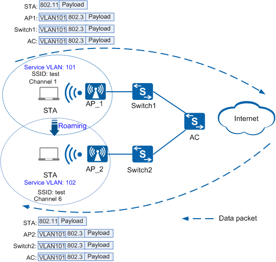
As shown in Figure 1, in direct forwarding mode, when a STA roams from AP_1 to AP_2 and the data packets arrive at AP2, AP_2 tags the packets with VLAN101 and forwards them to the upper-level network. When a STA roams from AP_2 to AP_1 and the data packets arrive at AP_1, AP_1 tags the packets with VLAN102 and forwards them to the upper-level network.
Figure 1 Networking diagram of roaming between APs in different service VLANs in direct forwarding mode
If the direct forwarding mode is used, configure the interfaces on Switch1 and Switch2 between the APs and AC and the AC interfaces (including the uplink, and downlink interfaces) to permit packets from VLAN101 and VLAN102 to pass through.

If no switch exists between the APs and AC, configure the AC interfaces (including the uplink, and downlink interfaces) to permit packets from VLAN101 and VLAN102 to pass through.
Tunnel forwarding mode
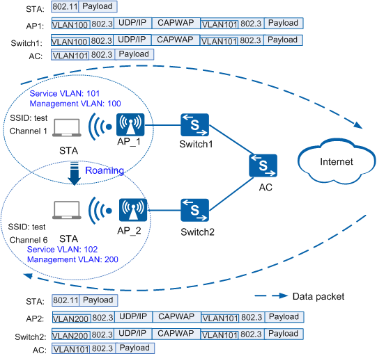
As shown in Figure 2, in tunnel forwarding mode, when a STA roams from AP_1 to AP_2 and the data packets arrive at AP_2, AP_2 tags the packets with VLAN101, encapsulates the packets in the CAPWAP tunnel, tags the packets with VLAN200, and forwards them to the AC. When the packets arrive at the AC, the AC decapsulates the CAPWAP packets, and forwards the packets to the upper-level network device. When a STA roams from AP_2 to AP_1 and the data packets arrive at AP_1, AP_1 tags the packets with VLAN102, encapsulates the packets in the CAPWAP tunnel, tags the packets with VLAN100, and forwards them to the AC. When the packets arrive at the AC, the AC decapsulates the CAPWAP packets, and forwards the packets to the upper-level network device.
Figure 2 Networking diagram of roaming between APs in different service VLANs in tunnel forwarding mode
If the tunnel forwarding mode is used, configure the uplink interface on the AC to permit packets from VLAN101 and VLAN102 to pass through.