Example for Configuring Portal Authentication to Control User Access to the Enterprise Network (Authentication Point on Aggregation Switch)
Portal Authentication Overview
Portal authentication is a Network Admission Control (NAC) method. Portal authentication is also called web authentication. Generally, Portal authentication websites are referred to as Portal websites. Users must be authenticated by the Portal websites before they can use network services.
Portal authentication is insecure, but allows flexible networking as no client software is required on users' terminals. 802.1X authentication is another NAC method. It is more secure than Portal authentication, but requires the installation of client software on users' terminals, resulting in networking inflexibility. Like Portal authentication, MAC address authentication also does not require the installation of client software, but user terminals' MAC addresses must be registered on the authentication server. Network configuration and management is complex.
Portal authentication applies to the users who are sparsely distributed and move frequently, for example, guests of a company.
Configuration Notes
- This configuration example applies to all switches running V200R009C00 or a later version.
- Huawei's Agile Controller-Campus in V100R001 functions as the Portal server and RADIUS server in this example. For the Agile Controller-Campus, the version required is V100R001, V100R002, V100R003.
- The RADIUS authentication and accounting shared keys and Portal shared key on the switch must be the same as those on the Agile Controller-Campus server.
- By default, the switch allows the packets from RADIUS and Portal servers to pass. You do not need to configure authentication-free rules for the two servers on the switch.
- When you run the access-user arp-detect command to configure the IP address and MAC address of the user gateway as the source IP address and source MAC address of user offline detection packets, ensure that the MAC address of the gateway remains unchanged, especially in active/standby switchover scenarios. If the gateway MAC address is changed, ARP entries of terminals will be incorrect on the device, and the terminals cannot communicate with the device.
Networking Requirements
- The authentication operations should be simple. The authentication system only performs access authorization. Minimum client software is installed on user terminals.
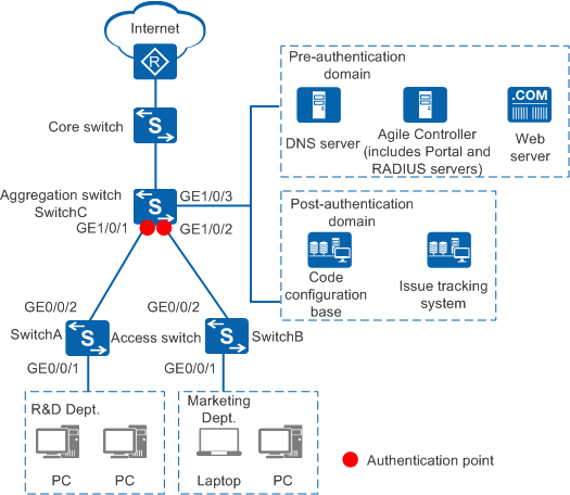
- Moderate security control is required. To facilitate maintenance, a moderate number of authentication points need to be deployed on the aggregation switch.
- A unified identity authentication mechanism is used to authenticate all terminals accessing the campus network and deny access from unauthorized terminals.
- R&D employees can connect only to public servers (such as the web and DNS servers) of the enterprise before the authentication, and can connect to both the intranet (code library and issue tracking system) and Internet after being authenticated.
- Marketing employees can connect only to public servers (such as the web and DNS servers) of the enterprise before the authentication, and can connect only to the Internet after being authenticated.
Data Plan
VLAN ID |
Function |
|---|---|
101 |
VLAN for R&D employees |
102 |
VLAN for marketing employees |
103 |
VLAN to which interfaces connecting to the servers belong |
Item |
Data |
Description |
|
|---|---|---|---|
Access switch (connecting to the R&D department) |
Interface number: GE0/0/1 VLAN: 101 |
Connects to employees' PCs. |
|
Interface number: GE0/0/2 VLAN: 101 |
Connects to the aggregation switch. |
||
Access switch (connecting to the marketing department) |
Interface number: GE0/0/1 VLAN: 102 |
Connects to employees' PCs. |
|
Interface number: GE0/0/2 VLAN: 102 |
Connects to the aggregation switch. |
||
Aggregation switch |
Interface number: GE1/0/1 VLAN: 101 VLANIF101 IP address: 192.168.0.1 |
Connects to the access switch of the R&D department. Functions as the gateway for R&D employees. |
|
Interface number: GE1/0/2 VLAN: 102 VLANIF102 IP address: 192.168.1.1 |
Connects to the access switch of the marketing department. Functions as the gateway for marketing employees. |
||
Interface number: GE1/0/3 VLAN: 103 VLANIF103 IP address: 172.16.1.254 |
Connects to the enterprise server area. Functions as the gateway for servers. |
||
Server |
Agile Controller-Campus (RADIUS server + Portal server) |
IP address: 172.16.1.1 |
- |
DNS server |
IP address: 172.16.1.2 |
- |
|
Web server |
IP address: 172.16.1.3 |
- |
|
Code library |
IP address: 172.16.1.4 |
- |
|
Issue tracking system |
IP address: 172.16.1.5 |
- |
|
Item |
Data |
Description |
|---|---|---|
Aggregation switch |
Number of the ACL for R&D employees' post-authentication domain: 3001 |
You need to enter this ACL number when configuring authorization rules and results on the Agile Controller-Campus. |
Number of the ACL for marketing employees' post-authentication domain: 3002 |
You need to enter this ACL number when configuring authorization rules and results on the Agile Controller-Campus. |
|
Authentication server:
|
|
|
Accounting server:
|
||
Portal server:
|
||
Agile Controller-Campus |
Host name: access.example.com |
Users can use the domain name to access the Portal server. |
Device IP address: 172.16.1.254 |
- |
|
Authentication port: 1812 |
- |
|
Accounting port: 1813 |
- |
|
RADIUS shared key: Admin@123 |
The RADIUS shared key must be the same as that configured on the switch. |
|
Port number that the Portal server uses to receive packets: 50200 |
- |
|
Portal shared key: Admin@123 |
It must be the same as the Portal authentication shared key configured on the switch. |
|
Department: R&D
Department: Marketing
|
Two departments and two corresponding accounts have been created on the Agile Controller-Campus: R&D department and an R&D employee account A-123; Marketing department and a marketing employee account B-123. |
|
Pre-authentication domain |
Agile Controller-Campus (including RADIUS server and Portal server), DNS server, and web server |
- |
Post-authentication domain |
|
- |
Configuration Roadmap
- Configure the access switch and aggregation switch to ensure network connectivity.
- Configure Portal authentication on the aggregation switch to implement user access control. Configure parameters for connecting to the RADIUS server and those for connecting to the Portal server, enable Portal authentication, and configure network access rights for the pre-authentication domain and post-authentication domain.
- Configure the Agile Controller-Campus:
- Log in to the Agile Controller-Campus.
- Add user accounts to the Agile Controller-Campus.
- Add a switch to the Agile Controller-Campus and configure related parameters to ensure normal communication between the Agile Controller-Campus and switch.
- Add authorization results and authorization rules to the Agile Controller-Campus to grant different access rights to R&D employees and marketing employees after they are successfully authenticated.
Procedure
- Configure the access switch to ensure network connectivity.
The following provides the configuration for SwitchA, the access switch connecting to the R&D department. The configuration for SwitchB, the access switch connecting to the marketing department, is similar.
<HUAWEI> system-view
[HUAWEI] sysname SwitchA
[SwitchA] vlan 101
[SwitchA-vlan101] quit
[SwitchA] interface gigabitethernet 0/0/1    //Interface connected to the R&D department
[SwitchA-GigabitEthernet0/0/1] port link-type access
[SwitchA-GigabitEthernet0/0/1] port default vlan 101
[SwitchA-GigabitEthernet0/0/1] quit
[SwitchA] interface gigabitethernet 0/0/2    //Interface connected to the aggregation switch
[SwitchA-GigabitEthernet0/0/2] port link-type trunk
[SwitchA-GigabitEthernet0/0/2] port trunk allow-pass vlan 101
[SwitchA-GigabitEthernet0/0/2] quit
- Configure the aggregation switch.
- Configure the Agile Controller-Campus.
- Create departments and accounts. The following describes how to create the R&D department. Create the Marketing department similarly.
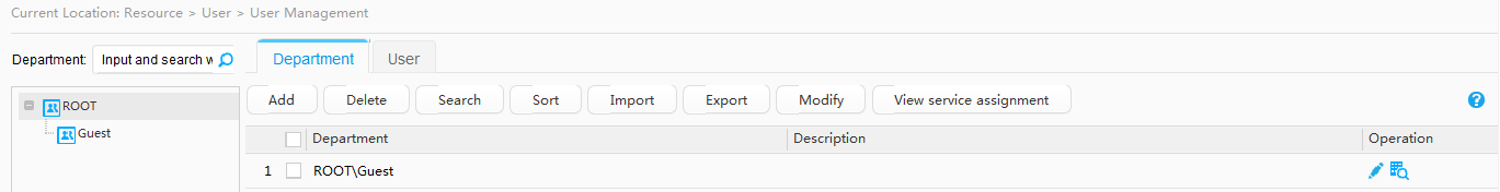
- Choose Resource > User > User Management.
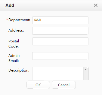
- Click the Department tab in the operation area on the right. Then click Add under the Department tab, and add the department R&D.
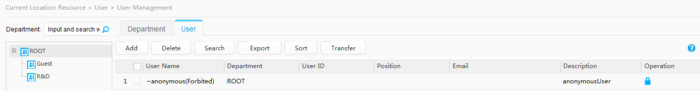
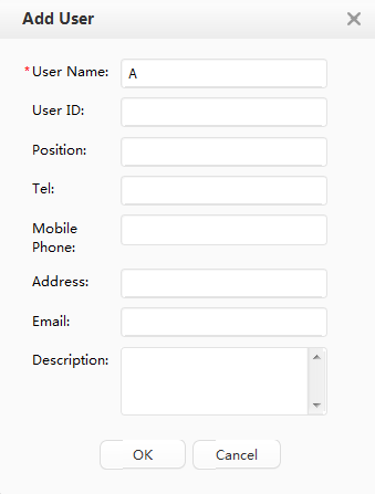
- Click the User tab in the operation area on the right. Then click Add under the User tab, and add the user A.
- Click
 in the Operation column on the right of user A. The Account Management page is displayed. Click Add, and create a common account A-123 with the password Huawei123.
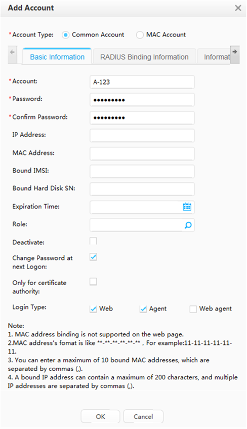
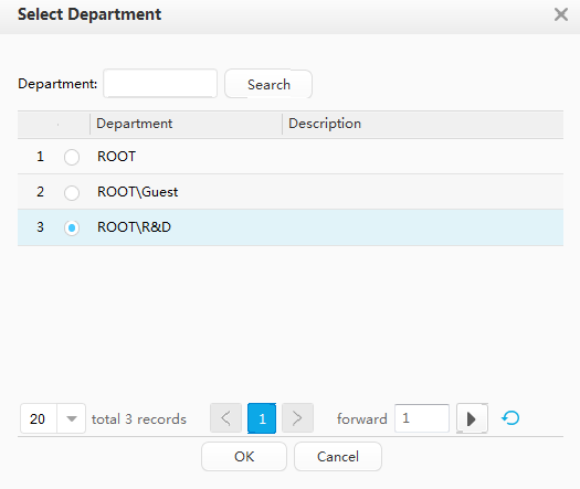
- On the User tab page, select user A and click Transfer to add user A to the R&D department.
- Add a switch to the Agile Controller-Campus and configure related parameters to ensure normal communication between the Agile Controller-Campus and switch.
- Choose Resource > Device > Device Management.
- Click Add.
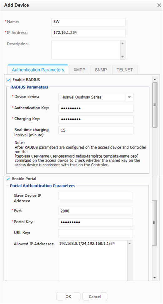
- Configure parameters for the switch.
Parameter
Value
Description
Name
SW
-
IP Address
172.16.1.254
The interface must be able to communicate with the SC.
Device series
Huawei Quidway Series
-
Authentication Key
Admin@123
It must be the same as the shared key of the RADIUS authentication server configured on the switch.
Charging Key
Admin@123
It must be the same as the shared key of the RADIUS accounting server configured on the switch.
Real-time charging interval (minute)
15
It must be the same as the real-time accounting interval configured on the switch.
Port
2000
This is the port that the switch uses to communicate with the Portal server. Retain the default value.
Portal Key
Admin@123
It must be the same as the Portal shared key configured on the switch.
Allowed IP Addresses
192.168.0.1/24; 192.168.1.1/24
-
- Click OK.
- Configure employee authorization. This example describes how to configure R&D employee authorization. The configuration procedure for marketing employees is the same, except that the network resources the two types of employees can access are different.
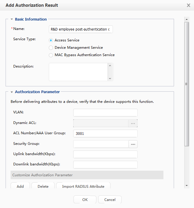
- Choose Policy > Permission Control > Authentication and Authorization > Authorization Result, and configure resources that R&D employees can access after authentication and authorization.
Parameter
Value
Description
Name
R&D employee post-authentication domain
-
Service Type
Access Service
-
ACL Number/AAA User Group
3001
The ACL number must be the same as the number of the ACL configured for R&D employees on the switch.
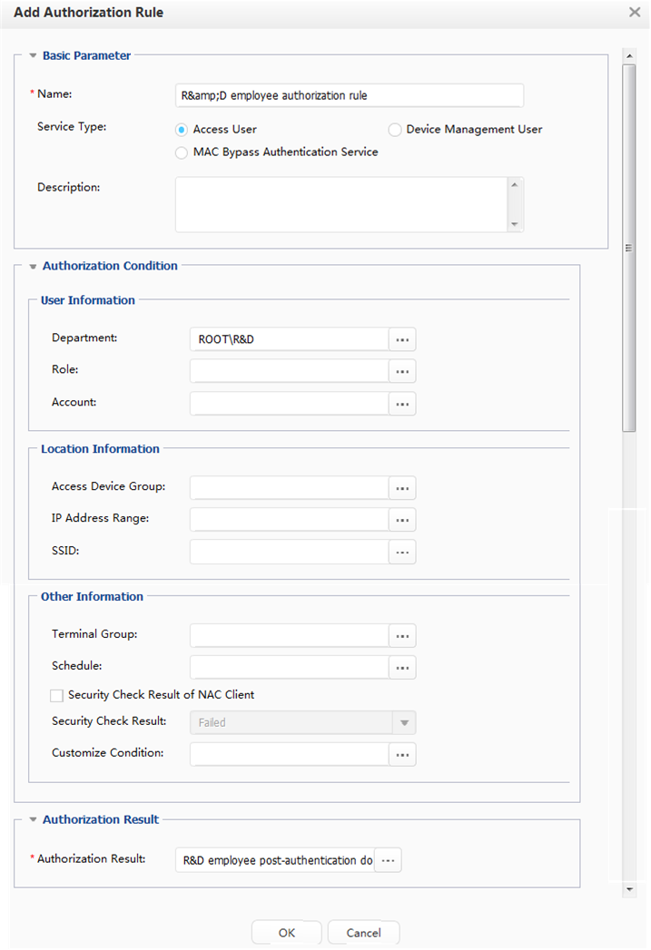
- Choose Policy > Permission Control > Authentication and Authorization > Authorization Rule, and specify the authorization conditions for R&D employees.
Parameter
Value
Description
Name
R&D employee authorization rule
-
Service Type
Access User
-
Department
R&D
-
Authorization Result
R&D employee post-authentication domain
-
- Choose Policy > Permission Control > Authentication and Authorization > Authorization Result, and configure resources that R&D employees can access after authentication and authorization.
- Create departments and accounts. The following describes how to create the R&D department. Create the Marketing department similarly.
- Verify the configuration.
- Employees can access only the Agile Controller-Campus, DNS, and web servers before authentication.
- The Portal authentication page is pushed to an employee when the employee attempts to visit an Internet website. After the employee enters the correct account and password, the requested web page is displayed.
- R&D employee A can access the Internet, code library, and issue tracking system after authentication. Marketing employee B can access the Internet but not the code library and issue tracking system after authentication.
- After an employee is authenticated, run the display access-user command on the switch. The command output shows that the employee is online.
Switch Configuration File
#
sysname SwitchA
#
vlan batch 101
#
interface GigabitEthernet0/0/1
 port link-type access
 port default vlan 101
#
interface GigabitEthernet0/0/2
 port link-type trunk
 port trunk allow-pass vlan 101
#
return
#
sysname SwitchB
#
vlan batch 102
#
interface GigabitEthernet0/0/1
 port link-type access
 port default vlan 102
#
interface GigabitEthernet0/0/2
 port link-type trunk
 port trunk allow-pass vlan 102
#
return
# Configuration file of the aggregation switch
#
sysname SwitchC
#
vlan batch 101 to 103
#
domain portal
#
access-user arp-detect vlan 101 ip-address 192.168.0.1 mac-address 2222-1111-1234
access-user arp-detect vlan 102 ip-address 192.168.1.1 mac-address 2222-1111-1234
#
dhcp enable
#
radius-server template policy
 radius-server shared-key cipher %#%#lJIB8CQ<:A;x$h2V5+;+C>HwC+@XAL)ldpQI}:$X%#%#
 radius-server authentication 172.16.1.1 1812 source ip-address 172.16.1.254 weight 80
 radius-server accounting 172.16.1.1 1813 source ip-address 172.16.1.254 weight 80
#
acl number 3001
 rule 1 permit ip
acl number 3002
 rule 1 deny ip destination 172.16.1.4 0
 rule 2 deny ip destination 172.16.1.5 0
 rule 3 permit ip
#
web-auth-server portal_huawei
 server-ip 172.16.1.1
 port 50200
 shared-key cipher %#%#q9a^<=Ct5'=0n40/1g}/m6Mo,U9u5!s(GYM}Z{<~%#%#
 url http://access.***.com:8080/portal
 source-ip 172.16.1.254
#
aaa
 authentication-scheme auth
  authentication-mode radius
 accounting-scheme acco
  accounting-mode radius
  accounting realtime 15
 domain portal
  authentication-scheme auth
  accounting-scheme acco
  radius-server policy
#
interface Vlanif101
 ip address 192.168.0.1 255.255.255.0
 web-auth-server portal_huawei direct
 authentication portal
 dhcp select interface
 dhcp server dns-list 172.16.1.2
#
interface Vlanif102
 ip address 192.168.1.1 255.255.255.0
 web-auth-server portal_huawei direct
 authentication portal
 dhcp select interface
 dhcp server dns-list 172.16.1.2
#
interface Vlanif103
 ip address 172.16.1.254 255.255.255.0
#
interface GigabitEthernet1/0/1
 port link-type trunk
 port trunk allow-pass vlan 101
#
interface GigabitEthernet1/0/2
 port link-type trunk
 port trunk allow-pass vlan 102
#
interface GigabitEthernet1/0/3
 port link-type access
 port default vlan 103
#
authentication free-rule 1 destination ip 172.16.1.2 mask 255.255.255.255
authentication free-rule 2 destination ip 172.16.1.3 mask 255.255.255.255
portal quiet-period
portal timer quiet-period 240
portal quiet-times 5
#
return