Example for Configuring Portal Authentication to Control User Access
Portal Authentication Overview
As one of NAC authentication modes, Portal authentication is also called web authentication. Generally, Portal authentication websites are also called Portal websites. When users go online, they must be authenticated on Portal websites. The users can use network resources only after they pass the authentication.
Portal authentication cannot ensure high security, but it does not require client software installation and provides flexible deployment. Another two NAC authentication methods have their advantages and disadvantages: 802.1X authentication ensures high security, but it requires that 802.1X client software be installed on user terminals, causing inflexible network deployment. MAC address authentication does not require client software installation, but MAC addresses must be registered on an authentication server, resulting in complex management.
Portal authentication is applied to scenarios where a large number of scattered users such as company visitors move frequently.
Configuration Notes
This configuration example applies to all switches running all versions.
When you run the access-user arp-detect command to configure the IP address and MAC address of the user gateway as the source IP address and source MAC address of user offline detection packets, ensure that the MAC address of the gateway remains unchanged, especially in active/standby switchover scenarios. If the gateway MAC address is changed, ARP entries of terminals will be incorrect on the device, and the terminals cannot communicate with the device.
Networking Requirements
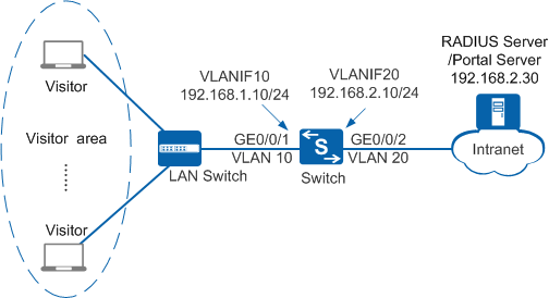
As shown in Figure 1, terminals in a company's visitor area are connected to the company's internal network through the Switch. Unauthorized access to the internal network can damage the company's service system and cause leakage of key information. Therefore, the administrator requires that the Switch should control users' network access rights to ensure internal network security.
Because visitors move frequently, Portal authentication is configured and the RADIUS server is used to authenticate user identities.
Configuration Roadmap
The configuration roadmap is as follows:
- Configure network interoperation.
- Configure AAA on the Switch to implement identity authentication on access users through the RADIUS server. The configuration includes configuring a RADIUS server template, an AAA scheme, and an authentication domain, and binding the RADIUS server template and AAA scheme to the authentication domain.
- Configure Portal authentication to control network access rights of the visitors in the visitor area. The configuration includes:
- Configure a Portal server template
- Configure a Portal access profile.
- Configure an authentication profile.
- Enable Portal authentication on an interface.

Before performing operations in this example, ensure that user access terminals and the server can communicate.
This example only provides the configuration of the Switch. The configurations of the LAN Switch and server are not provided here.
Procedure
- Create VLANs and configure the VLANs allowed by interfaces so that packets can be forwarded.
# Create VLAN 10 and VLAN 20.
<HUAWEI> system-view
[HUAWEI] sysname Switch
[Switch] vlan batch 10 20
# Configure GE0/0/1 connecting the Switch to users as an access interface and add the interface to VLAN 10.
[Switch] interface gigabitethernet0/0/1
[Switch-GigabitEthernet0/0/1] port link-type access
[Switch-GigabitEthernet0/0/1] port default vlan 10
[Switch-GigabitEthernet0/0/1] quit
[Switch] interface vlanif 10
[Switch-Vlanif10] ip address 192.168.1.10 24
[Switch-Vlanif10] quit
# Configure GE0/0/2 connecting the Switch to the RADIUS server as an access interface and add the interface to VLAN 20.
[Switch] interface gigabitethernet0/0/2
[Switch-GigabitEthernet0/0/2] port link-type access
[Switch-GigabitEthernet0/0/2] port default vlan 20
[Switch-GigabitEthernet0/0/2] quit
[Switch] interface vlanif 20
[Switch-Vlanif20] ip address 192.168.2.10 24
[Switch-Vlanif20] quit
- Configure AAA.
# Create and configure the RADIUS server template rd1.
[Switch] radius-server template rd1
[Switch-radius-rd1] radius-server authentication 192.168.2.30 1812
[Switch-radius-rd1] radius-server shared-key cipher Huawei@2012
[Switch-radius-rd1] quit
# Create the AAA authentication scheme abc and set the authentication mode to RADIUS.
[Switch] aaa
[Switch-aaa] authentication-scheme abc
[Switch-aaa-authen-abc] authentication-mode radius
[Switch-aaa-authen-abc] quit
# Create the authentication domain huawei.com, and bind the AAA authentication scheme abc and RADIUS server template rd1 to the domain.
[Switch-aaa] domain huawei.com
[Switch-aaa-domain-huawei.com] authentication-scheme abc
[Switch-aaa-domain-huawei.com] radius-server rd1
[Switch-aaa-domain-huawei.com] quit
[Switch-aaa] quit
# Check whether a user can pass RADIUS authentication. The test user test and password Huawei2012 have been configured on the RADIUS server.
[Switch] test-aaa test Huawei2012 radius-template rd1
Info: Account test succeeded.
- Configure Portal authentication.# Set the NAC mode to unified.
[Switch] authentication unified-mode
- By default, the unified mode is used.
- After changing the NAC mode from common to unified, save the configuration and restart the device to make the configuration take effect.
# Configure the Portal server template abc.[Switch] web-auth-server abc [Switch-web-auth-server-abc] server-ip 192.168.2.30 [Switch-web-auth-server-abc] port 50200 [Switch-web-auth-server-abc] url http://192.168.2.30:8080/portal [Switch-web-auth-server-abc] shared-key cipher Huawei@123 [Switch-web-auth-server-abc] quit
Ensure that the port number configured on the device is the same as the port number used by the Portal server.
# Configure the Portal access profile web1.
[Switch] portal-access-profile name web1
[Switch-portal-acces-profile-web1] web-auth-server abc direct
[Switch-portal-acces-profile-web1] quit
# Configure the authentication profile p1, bind the Portal access profile web1 to the authentication profile, specify the domain huawei.com as the forcible authentication domain in the authentication profile, set the user access mode to multi-authen, and set the maximum number of access users to 100.
[Switch] authentication-profile name p1
[Switch-authen-profile-p1] portal-access-profile web1
[Switch-authen-profile-p1] access-domain huawei.com force
[Switch-authen-profile-p1] authentication mode multi-authen max-user 100
[Switch-authen-profile-p1] quit
In this example, users are allocated static IP addresses. If the users obtain IP addresses through DHCP and the DHCP server is on the upstream network of the NAS device, use the free-rule command to create authentication-free rules and ensure that the DHCP server is included in the authentication-free rules.
In versions earlier than V200R012C00, if the URL of Portal server needs to be analyzed by DNS and the DNS server is on the upstream network of the NAS device, you also need to create authentication-free rules and ensure that the DNS server is included in the authentication-free rules. In V200R012C00 and later versions, the NAS device automatically allows DNS packets to pass through and no authentication-free rule is required in Portal authentication.
# Bind the authentication profile p1 to GE0/0/1 and enable Portal authentication on the interface.
[Switch] interface gigabitethernet0/0/1
[Switch-GigabitEthernet0/0/1] authentication-profile p1
[Switch-GigabitEthernet0/0/1] quit
# (Recommended) Configure the source IP address and source MAC address for offline detection packets in a specified VLAN. You are advised to set the user gateway IP address and its corresponding MAC address as the source IP address and source MAC address of offline detection packets. This function does not take effect for users who use Layer 3 Portal authentication.
[Switch] access-user arp-detect vlan 10 ip-address 192.168.1.10 mac-address 2222-1111-1234
- Verify the configuration.
- After a user opens the browser and enters any website address, the user is redirected to the Portal authentication page. The user then can enter the user name and password for authentication.
- If the user name and password are correct, an authentication success message is displayed on the Portal authentication page. The user can access the network.
- After users go online, you can run the display access-user access-type portal command on the device to view information about online Portal authentication users.
Configuration Files
Configuration file of the Switch
#
sysname Switch
#
vlan batch 10 20
#
authentication-profile name p1
 portal-access-profile web1
 authentication mode multi-authen max-user 100
 access-domain huawei.com force
#
access-user arp-detect vlan 10 ip-address 192.168.1.10 mac-address 2222-1111-1234
#
radius-server template rd1
 radius-server shared-key cipher %#%#4*SO-2u,Q.\1C~%[eiB77N/^2wME;6t%6U@qAJ9:%#%#
 radius-server authentication 192.168.2.30 1812 weight 80
#
web-auth-server abc
 server-ip 192.168.2.30
 port 50200
 shared-key cipher %#%#CR@WPM9Q30%]A}9]g4hUqe1u~4Fz}PlU)QPL;73#%#%#
 url http://192.168.2.30:8080/portal
#
portal-access-profile name web1
 web-auth-server abc direct
#
aaa
 authentication-scheme abc
  authentication-mode radius
 domain huawei.com
  authentication-scheme abc
  radius-server rd1
#
interface Vlanif10
 ip address 192.168.1.10 255.255.255.0
#
interface Vlanif20
 ip address 192.168.2.10 255.255.255.0
#
interface GigabitEthernet0/0/1
 port link-type access
 port default vlan 10
 authentication-profile p1
#
interface GigabitEthernet0/0/2
 port link-type access
 port default vlan 20
#
return