Configuring 802.1X and MAC Address Authentication for Access Users on Huawei Agile Controller-Campus
Overview
On a NAC network, the 802.1X, MAC address, and Portal authentication modes are configured on the user access interfaces of a device to meet various authentication requirements. Users can access the network using any authentication mode.
If multiple authentication modes are enabled, the authentication modes take effect in the sequence they are configured. In addition, after multiple authentication modes are deployed, users can be authenticated in different modes by default and assigned different network rights accordingly by the device.
Networking Requirements
Enterprises have high requirements on network security. To prevent unauthorized access and protect information security, an enterprise requests users to pass identity authentication and security check before they access the enterprise network. Only authorized users are allowed to access the enterprise network.
In addition, dumb terminals, such as IP phones and printers, can access the enterprise network only after passing authentication.
The enterprise network has the following characteristics:
The access switches on the network do not support 802.1X authentication.
The enterprise network has a small size and does not have branch networks.
The enterprise has no more than 1000 employees. A maximum of 2000 users, including guests, access the network every day.
Dumb terminals, such as IP phones and printers, are connected to the enterprise network.
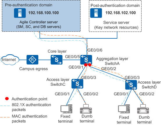
To reduce network reconstruction investment, you are advised to configure the 802.1X authentication function on the aggregation switch and connect a single centralized authentication server to the aggregation switch in bypass mode. MAC address authentication needs to be configured for dumb terminals.
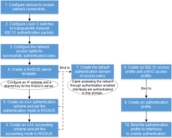
Configuration Logic
Item |
Description |
|---|---|
Creating a department and an account |
- |
Adding switches |
Set parameters for switches connected to the Agile Controller-Campus. |
Adding an authentication rule |
Configure the conditions for users to pass the authentication. |
Adding an authorization result |
Create network access right profiles so that users granted with different profiles have different network access rights. |
Adding an authorization rule |
Select network access right profiles and users in an authorization rule so that specified network access rights are granted to specific users. |
Configuration Notes
This configuration example applies to all switches running V200R009C00 or a later version, Huawei Agile Controller-Campus in V100R001 functions as the RADIUS server. For the Agile Controller-Campus, the version required is V100R001, V100R002, V100R003.
The RADIUS authentication and accounting shared keys and Portal shared key on the switch must be the same as those on the Agile Controller-Campus server.
By default, the switch allows the packets from RADIUS server to pass. You do not need to configure authentication-free rules for the server on the switch.
When you run the access-user arp-detect command to configure the IP address and MAC address of the user gateway as the source IP address and source MAC address of user offline detection packets, ensure that the MAC address of the gateway remains unchanged, especially in active/standby switchover scenarios. If the gateway MAC address is changed, ARP entries of terminals will be incorrect on the device, and the terminals cannot communicate with the device.
Data Plan
Item |
Data |
|---|---|
Agile Controller-Campus |
IP address: 192.168.100.100 |
Post-authentication domain server |
IP address: 192.168.102.100 |
Aggregation switch (SwitchA) |
|
Access switch (SwitchC) |
User VLAN ID: 200 |
Access switch (SwitchD) |
User VLAN ID: 200 |
Item |
Data |
|---|---|
RADIUS scheme |
|
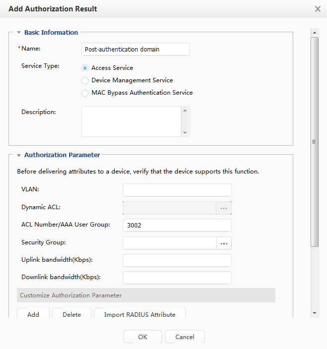
ACL number of the post-authentication domain |
3002 |
Item |
Data |
|---|---|
Department |
R&D department |
Access user |
User name: A Wired access account: A-123 Password: Huawei123 |
Device group |
Wired device group: Switch |
| Switch IP address | SwitchA: 192.168.10.10 |
RADIUS authentication key |
Huawei@2014 |
Charging Key |
Huawei@2014 |
Procedure
- Configure the access switches.
- Configure the device to transparently transmit 802.1X packets. This example uses SwitchC to describe the configuration. The configuration on SwitchD is the same as that on SwitchC.

In this example, SwitchC and SwitchD are deployed between the authentication switch SwitchA and users. 802.1X packet transparent transmission needs to be configured on SwitchC and SwitchD so that SwitchA can perform 802.1X authentication for users.
- Method 1:
[SwitchC] l2protocol-tunnel user-defined-protocol 802.1X protocol-mac 0180-c200-0003 group-mac 0100-0000-0002
[SwitchC] interface gigabitethernet 0/0/1
[SwitchC-GigabitEthernet0/0/1] l2protocol-tunnel user-defined-protocol 802.1X enable
[SwitchC-GigabitEthernet0/0/1] bpdu enable
[SwitchC-GigabitEthernet0/0/1] quit
[SwitchC] interface gigabitethernet 0/0/2
[SwitchC-GigabitEthernet0/0/2] l2protocol-tunnel user-defined-protocol 802.1X enable
[SwitchC-GigabitEthernet0/0/2] bpdu enable
[SwitchC-GigabitEthernet0/0/2] quit
[SwitchC] interface gigabitethernet 0/0/3
[SwitchC-GigabitEthernet0/0/3] l2protocol-tunnel user-defined-protocol 802.1X enable
[SwitchC-GigabitEthernet0/0/3] bpdu enable
[SwitchC-GigabitEthernet0/0/3] quit
Method 2: This method is recommended when a large number of users exist or high network performance is required. Only the S5720-EI, S5720-HI, S5730-HI, S5731-H, S5731S-H, S5731-S, S5731S-S, S6720-EI, S6720-HI, S6720S-EI, S5732-H, S6730-H, S6730S-H, S6730-S, and S6730S-S support this method.
[SwitchC] undo bpdu mac-address 0180-c200-0000 ffff-ffff-fff0
[SwitchC] bpdu mac-address 0180-c200-0000 FFFF-FFFF-FFFE
[SwitchC] bpdu mac-address 0180-c200-0002 FFFF-FFFF-FFFF
[SwitchC] bpdu mac-address 0180-c200-0004 FFFF-FFFF-FFFC
[SwitchC] bpdu mac-address 0180-c200-0008 FFFF-FFFF-FFF8
This following step is mandatory when you switch from method 1 to method 2.
[SwitchC] interface gigabitethernet 0/0/1
[SwitchC-GigabitEthernet0/0/1] undo l2protocol-tunnel user-defined-protocol 802.1X enable
[SwitchC-GigabitEthernet0/0/1] quit
[SwitchC] interface gigabitethernet 0/0/2
[SwitchC-GigabitEthernet0/0/2] undo l2protocol-tunnel user-defined-protocol 802.1X enable
[SwitchC-GigabitEthernet0/0/2] quit
[SwitchC] interface gigabitethernet 0/0/3
[SwitchC-GigabitEthernet0/0/3] undo l2protocol-tunnel user-defined-protocol 802.1X enable
[SwitchC-GigabitEthernet0/0/3] quit
- Method 1:
- Configure the device to transparently transmit 802.1X packets. This example uses SwitchC to describe the configuration. The configuration on SwitchD is the same as that on SwitchC.
- Configure the aggregation switch.
- Enable 802.1X and MAC address authentication.# Set the NAC mode to unified.
[SwitchA] authentication unified-mode
By default, the unified mode is enabled. After the NAC mode is changed, the device automatically restarts.
# Configure an 802.1X access profile. By default, an 802.1X access profile uses the EAP authentication mode. Ensure that the RADIUS server supports EAP; otherwise, the server cannot process 802.1X authentication request packets.
[SwitchA] dot1x-access-profile name d1
[SwitchA-dot1x-access-profile-d1] dot1x authentication-method eap
[SwitchA-dot1x-access-profile-d1] dot1x timer client-timeout 30
[SwitchA-dot1x-access-profile-d1] quit
# Configure a MAC access profile.[SwitchA] mac-access-profile name m1 [SwitchA-mac-access-profile-m1] mac-authen username fixed A-123 password cipher Huawei123 //Set the user name mode for MAC address authentication to fixed user name. Set the user name to A-123 and password to Huawei123. [SwitchA-mac-access-profile-m1] quit# Configure an authentication profile.[SwitchA] authentication-profile name p1 [SwitchA-authen-profile-p1] mac-access-profile m1 //Bind the MAC access profile m1. [SwitchA-authen-profile-p1] dot1x-access-profile d1 //Bind the 802.1X access profile d1. [SwitchA-authen-profile-p1] quit
# Enable 802.1X authentication and MAC address authentication on GE0/0/1 and GE0/0/2.[SwitchA] interface gigabitethernet 0/0/1 [SwitchA-Gigabitethernet0/0/1] authentication-profile p1 //Bind the authentication profile p1 and enable 802.1X + MAC address combined authentication. [SwitchA-Gigabitethernet0/0/1] quit [SwitchA] interface gigabitethernet 0/0/2 [SwitchA-Gigabitethernet0/0/2] authentication-profile p1 //Bind the authentication profile p1 and enable 802.1X + MAC address combined authentication. [SwitchA-Gigabitethernet0/0/2] quit
# (Recommended) Configure the source IP address and source MAC address for offline detection packets in a specified VLAN. You are advised to set the user gateway IP address and its corresponding MAC address as the source IP address and source MAC address of offline detection packets.
[SwitchA] access-user arp-detect vlan 200 ip-address 192.168.200.1 mac-address 2222-1111-1234
- Enable 802.1X and MAC address authentication.
- Configure the Agile Controller-Campus.
- Create a department and an account.
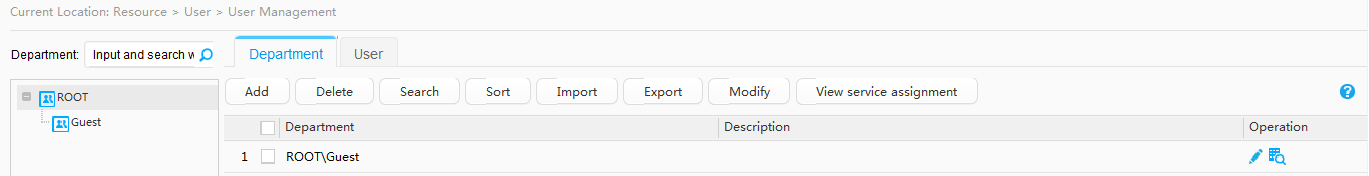
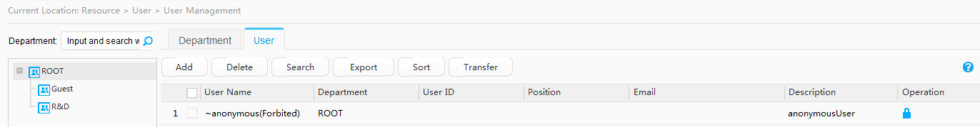
- Choose Resource > User > User Management.
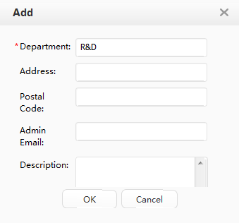
- Click the Department tab in the operation area on the right. Then click Add under the Department tab, and add the department R&D.
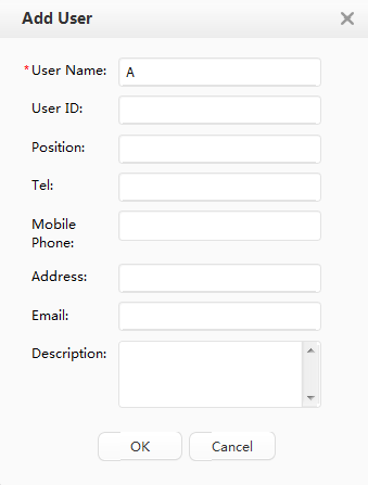
- Click the User tab in the operation area on the right. Then click Add under the User tab, and add the user A.
- Click
 in the Operation column on the right of user A. The Account Management page is displayed. Click Add, and create a common account A-123 with the password Huawei123.
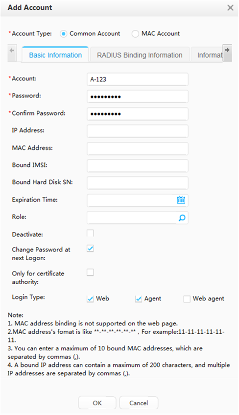
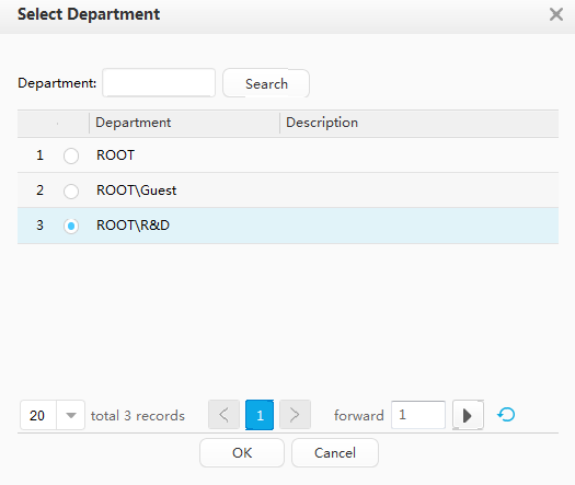
- On the User tab page, select user A and click Transfer to add user A to the R&D department.
- Add switches to the Agile Controller-Campus so that the switches can communicate with the Agile Controller-Campus.
Click Permission Control Device Group in the navigation tree, and click
 and Add SubGroup to create a device group Switch.
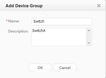
Click the device group in the navigation tree and select ALL Device. Click Add to add network access devices.
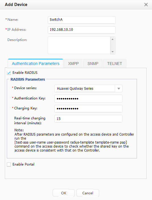
Set connection parameters on the Add Device page.
Parameter
Value
Description
Name
SwitchA
-
IP Address
192.168.10.10
The interface on the switch must communicate with the Agile Controller-Campus.
Device Series Huawei Quidway series switch -
Authentication Key
Huawei@2014
It must be the same as the shared key of the RADIUS authentication server configured on the switch.
Charging Key
Huawei@2014
It must be the same as the shared key of the RADIUS accounting server configured on the switch.
Real-time charging interval (minute)
15
It must be the same as the real-time accounting interval configured on the switch.
- Click Permission Control Device Group in the navigation tree, select SwitchC, and click Move to move SwitchA to the Switch group. The configuration on SwitchD is the same as that on SwitchC.
- Add an authentication rule.
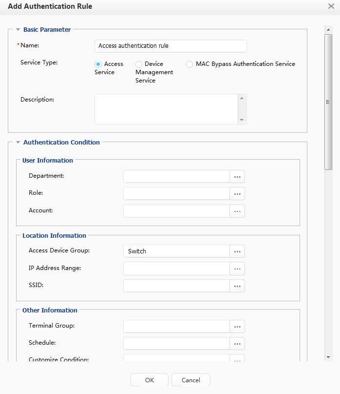
- Configure basic information for the authentication rule.
Parameter
Value
Description
Name Access authentication rule -
Service Type
Access service
-
Authentication Condition
Device group Switch
Customize authentication rules based on the requirements of your network.
Please select the allowed authentication protocol
- PAP
- CHAP
- EAP-MD5
- EAP-PEAP-MSCHAPv2
- EAP-TLS
- EAP-PEAP-GTC
- EAP-TTLS-PAP
-
- Add an authorization result.
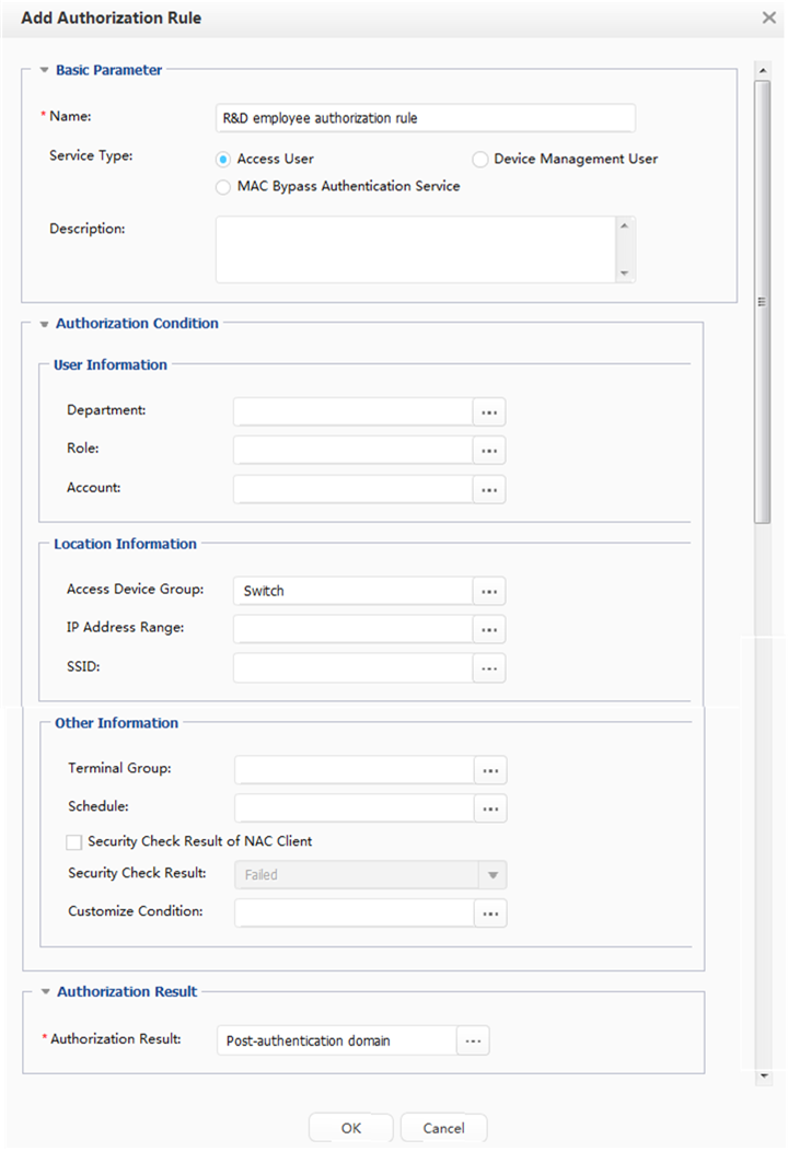
- Add an authorization rule.
After a user passes the authentication, authorization phase starts. The Agile Controller-Campus grants the user access rights based on the authorization rule.
- Create a department and an account.
- Verify the configuration.
- An employee can only access the Agile Controller-Campus server before passing the authentication.
- After passing the authentication, the employee can access resources in the post-authentication domain.
- After the employee passes the authentication, run the display access-user command on the switch. The command output shows information about the online employee.
Configuration Files
SwitchA configuration file
#
sysname SwitchA
#
vlan batch 100 200
#
authentication-profile name p1
 dot1x-access-profile d1
 mac-access-profile m1
#
domain isp
#
access-user arp-detect vlan 200 ip-address 192.168.200.1 mac-address 2222-1111-1234
#
radius-server template rd1
 radius-server shared-key cipher %#%#FP@&C(&{$F2HTlPxg^NLS~KqA/\^3Fex;T@Q9A](%#%#
 radius-server authentication 192.168.100.100 1812 weight 80
 radius-server accounting 192.168.100.100 1813 weight 80
#
dot1x-access-profile name d1
#
mac-access-profile name m1
 mac-authen username fixed A-123 password cipher %#%#'Fxw8E,G-81(A3U<^HH9Sj\:&hTdd>R>HILQYLtW%#%#
#
acl number 3002
 rule 1 permit ip destination 192.168.102.100 0
 rule 2 deny ip
#
aaa
 authentication-scheme abc
  authentication-mode radius
 accounting-scheme acco1
  accounting-mode radius
  accounting realtime 15
 domain isp
  authentication-scheme abc
  accounting-scheme acco1
  radius-server rd1
#
interface Vlanif100
 ip address 192.168.10.10 255.255.255.0
#
interface Vlanif200
 ip address 192.168.200.1 255.255.255.0
#
interface GigabitEthernet0/0/1
 port link-type trunk
 port trunk allow-pass vlan 200
 authentication-profile p1
#
interface GigabitEthernet0/0/2
 port link-type trunk
 port trunk allow-pass vlan 200
 authentication-profile p1
#
interface GigabitEthernet0/0/6
 port link-type trunk
 port trunk allow-pass vlan 100
#
ip route-static 192.168.100.0 255.255.255.0 192.168.10.10
ip route-static 192.168.102.0 255.255.255.0 192.168.10.10
#
return
SwitchC configuration file
#
sysname SwitchC
#
vlan batch 200
#
l2protocol-tunnel user-defined-protocol 802.1x protocol-mac 0180-c200-0003 group-mac 0100-0000-0002
#
interface GigabitEthernet0/0/1
 port link-type access
 port default vlan 200
 l2protocol-tunnel user-defined-protocol 802.1x enable
#
interface GigabitEthernet0/0/2
 port link-type access
 port default vlan 200
 l2protocol-tunnel user-defined-protocol 802.1x enable
#
interface GigabitEthernet0/0/3
 port link-type trunk
 port trunk allow-pass vlan 200
 l2protocol-tunnel user-defined-protocol 802.1x enable
#
return