Example for Deploying the Free Mobility Function for Users' Physical Location Change (V200R006C00, V200R007C00, V200R008C00)
Free Mobility Overview
In an enterprise network, different network access policies can be deployed for users on access devices to meet different network access requirements. The application of mobile office and BYOD technologies brings frequent changes of users' physical locations and IP addresses. Therefore, the original network control solution based on physical ports and IP addresses cannot ensure consistency of network access experience. For example, the network access policy of a user does not change when the user's physical location changes.
The free mobility solution allows a user to obtain the same network access policy regardless of the user's location and IP address changes.
The switches must be associated with the Agile Controller-Campus in the free mobility solution. An administrator only needs to uniformly deploy network access policies on the Agile Controller-Campus for users, and deliver the policies to all associated switches. Then, a user can obtain the same access policy no matter how the user's physical location and IP address change.
Configuration Notes
- Free mobility is supported only in NAC unified mode.
- The following table lists the applicable products and versions.
Table 1 Applicable products and versions Switch Version
Agile Controller-Campus Version
Switch Model
V200R006C00, V200R007C00
V100R001
- S5720-HI
- S7700 and S9700 that use X series cards
V200R008C00
V100R002C00, V100R002C10
When the controller delivers a UCL group name that is not supported by the switch, for example, this group name contains Chinese characters or special characters, the switch cannot parse the group name. A UCL group name that can be supported by the switch must be consistent with the value of group-name in the ucl-group group-index [ name group-name ] command, cannot be -, --, a, an, or any, and cannot contain any of the following characters: / \ : * ? " < > | @ ' %. Therefore, when configuring a UCL group name on the controller, do not use Chinese characters or special characters.
If the core switch has been associated with an Agile Controller-Campus and has free mobility configured, perform the following steps to delete historical data and reconfigure the core switch.
- Run the undo group-policy controller command in the system view to disable free mobility and disconnect the switch from the Agile Controller-Campus.
- Run the undo acl all command to delete the access control policy.
- Run the undo ucl-group ip all command to delete IP addresses bound to security groups.
- Run the undo ucl-group all command to delete security groups.
- Return to the user view and run the save command. The system automatically deletes the configured version number.
Networking Requirements
Employees in an enterprise connect to the network in wired and wireless modes and are authenticated using 802.1X or Portal authentication.
The employees do not work in fixed locations and want to obtain the same rights after being authenticated regardless of their access locations.
Requirement Analysis
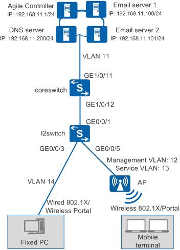
As shown in Figure 1, the agile core switch coreswitch (supporting native AC) functions as the authentication point and the access switch is a common switch.
You can configure 802.1X authentication and Portal authentication on the core switch so that wired and wireless users can connect to the network after being authenticated by the core switch.
You can configure free mobility so that users have the same rights and experience regardless of their access locations.
Data Plan
Item |
Data |
Description |
|
|---|---|---|---|
VLAN |
ID: 11 IP address: 192.168.11.254/24 |
The core switch uses this VLAN to communicate with the Agile Controller-Campus. |
|
ID: 12 IP address: 192.168.12.254/24 |
The core switch uses this VLAN to manage APs. |
||
ID: 13 IP address: 192.168.13.254/24 |
The core switch uses this VLAN to provide wireless access services. |
||
ID: 14 IP address: 192.168.14.254/24 |
The core switch uses this VLAN to provide wired access services. |
||
Core switch (coreswitch) |
Interface number: GE1/0/11 IDs of allowed VLANs: 11 |
This interface allows packets from planned VLANs to pass through. |
|
Interface number: GE1/0/12 IDs of allowed VLANs: 12, 14 |
This interface allows packets from the wired access service VLAN and APs' management VLAN to pass through. |
||
Access switch |
Interface number: GE0/0/1 IDs of allowed VLANs: 12, 14 |
This interface connects to GE1/0/12 on the core switch (coreswitch). |
|
Interface number: GE0/0/3 IDs of allowed VLANs: 14 |
This interface provides wired access and allows packets from the wired access service VLAN to pass through. |
||
Interface number: GE0/0/5 IDs of allowed VLANs: 12 |
This interface provides wireless access and allows packets from the APs' management VLAN to pass through. |
||
Server |
Agile Controller-Campus: 192.168.11.1 |
The Service Manager (SM) and Service Controller (SC) are installed on the same server. The SC functions as both the RADIUS server and Portal server. |
|
Email server 1: 192.168.11.100 Email server 2: 192.168.11.101 |
- |
||
DNS server: 192.168.11.200 |
– |
||
Item |
Data |
Description |
|---|---|---|
Core switch (coreswitch) |
RADIUS authentication server:
|
|
RADIUS accounting server:
|
||
Portal server:
|
||
XMPP password: Admin@123 |
The configuration is the same as that on the Agile Controller-Campus. |
|
Agile Controller-Campus |
Core switch's IP address: 192.168.11.254 |
This IP address is the IP address of VLANIF 11. |
RADIUS parameters:
|
The configuration is the same as that on the core switch. |
|
Portal parameters:
|
||
XMPP password: Admin@123 |
The configuration is the same as that on the core switch. |
|
Department: Employee |
Assume that the department Employee exists under ROOT. Configure free mobility for the department Employee in this example. |
|
Security group: Employee_Group Email server:
|
Use fast authorization to authorize the security group Employee_Group to the employee department. |
|
Post-authentication domain |
Email server |
Employees can access the email servers after being authenticated. |
Pre-authentication domain |
DNS server |
Employees can send domain names to the DNS server for resolution before being authenticated. |
Configuration Roadmap
Configure the core switch.
- Switch the NAC configuration mode to unified mode.
- Configure interfaces and VLANs, and enable the DHCP server function.
- Configure parameters for interoperation with the RADIUS server.
- Configure parameters for interoperation with the Portal server.
- Configure the access authentication point for fixed PCs.
- Configure an authentication-free rule.
- Configure AC system parameters to provide wireless access.
- Configure XMPP parameters for interoperation with the Agile Controller-Campus and enable free mobility.
Configure the access switch.
- Configure interfaces and VLANs to implement network communication.
- Configure the switch to transparently transmit 802.1X packets.
 In this example, the LAN switch exists between the core switch and users. To ensure that users can pass 802.1X authentication, you must configure the EAP packet transparent transmission function on the LAN switch.
- Run the l2protocol-tunnel user-defined-protocol 802.1x protocol-mac 0180-c200-0003 group-mac 0100-0000-0002 command in the system view of the LAN switch to configure the LAN switch to transparently transmit EAP packets.
- Run the l2protocol-tunnel user-defined-protocol 802.1x enable command on the interface connecting to users and the interface connecting to the access switch to enable the Layer 2 protocol tunneling function.
Configure the Agile Controller-Campus.
- Configure RADIUS, Portal, and XMPP parameters, and add the core switch.
- Configure security groups Employee_Group and Email_Server to indicate users and resources, respectively.
- Use fast authorization to authorize the security group Employee_Group to the employee department. Employees are mapped to the security group Employee_Group after being authenticated.
- Configure an access control policy to allow Employee_Group to access Email_Server.
Procedure
- Configure the core switch.
- Change the NAC configuration mode to unified mode.
You must switch the NAC configuration mode to unified mode on a switch with the free mobility function configured. The unified mode takes effect after the switch restarts.
<HUAWEI> system-view
[HUAWEI] sysname coreswitch
[coreswitch] authentication unified-mode
- Configure system parameters of the AC (coreswitch in this example) to implement wireless access.
- Configure the AC's country code, ID, and carrier ID.
[coreswitch] wlan ac-global country-code cn
[coreswitch] wlan ac-global ac id 1 carrier id other
- Configure VLANIF 12 as the AC's source interface.
[coreswitch] capwap source interface vlanif 12
- In V200R006 and earlier versions, run the wlan ac source interface vlanif 12 command in the WLAN view.
- In V200R007 and later versions, run the capwap source interface vlanif 12 command in the system view.
- Manage APs on the AC and check the ID corresponding to AP7110DN-AGN. The obtained AP's MAC address is dcd2-fc04-b4c0.
[coreswitch] display ap-type all      //Check supported AP types.
  All AP types information:
  ------------------------------------------------------------------------------
  ID     Type
  ------------------------------------------------------------------------------
  17     AP6010SN-GN
  19     AP6010DN-AGN
  21     AP6310SN-GN
  23     AP6510DN-AGN
  25     AP6610DN-AGN
  27     AP7110SN-GN
  28     AP7110DN-AGN
  29     AP5010SN-GN
  30     AP5010DN-AGN
  31     AP3010DN-AGN
  33     AP6510DN-AGN-US
  34     AP6610DN-AGN-US
  35     AP5030DN
  36     AP5130DN
  37     AP7030DE
  38     AP2010DN
  39     AP8130DN
  40     AP8030DN
  42     AP9330DN
  ------------------------------------------------------------------------------
  Total number: 19
[coreswitch] wlan
[coreswitch-wlan-view] ap-auth-mode mac-auth    //Set the AP authentication mode to MAC address authentication.
[coreswitch-wlan-view] ap id 1 type-id 28 mac dcd2-fc04-b4c0    //Add APs to the AC based on the AP type ID and MAC address.
[coreswitch-wlan-ap-1] quit
[coreswitch-wlan-view] ap-region id 10    //Create an AP domain.
[coreswitch-wlan-ap-region-10] quit
[coreswitch-wlan-view] ap id 1
[coreswitch-wlan-ap-1] region-id 10    //Add APs to the AP domain.
[coreswitch-wlan-ap-1] quit
[coreswitch-wlan-view] display ap all    //After APs are powered on, the command output shows that the AP state field displays normal.
  All AP(s) information:
  Normal[1],Fault[0],Commit-failed[0],Committing[0],Config[0],Download[0]
  Config-failed[0],Standby[0],Type-not-match[0],Ver-mismatch[0]
  ------------------------------------------------------------------------------
  AP    AP                    AP              Profile   AP              AP
                                              /Region
  ID    Type                  MAC             ID        State           Sysname
  ------------------------------------------------------------------------------
  1     AP7110DN-AGN          dcd2-fc04-b4c0    0/10    normal          ap-1
  ------------------------------------------------------------------------------
  Total number: 1,printed: 1
Adjusting the radio channel and power of an AP may lead to parameter adjustment of another AP. To quicken adjustment, minimize the impact, and reduce the workload, you are advised to divide all the APs accessing the same AC into several regions. The impact of adjustment on an AP is limited within the local region.
- Configure WLAN service parameters.
[coreswitch-wlan-view] wmm-profile name wmm id 1    //Create the WMM profile wmm.
[coreswitch-wlan-wmm-prof-wmm] quit
[coreswitch-wlan-view] radio-profile name radio id 31    //Create the radio profile radio.
[coreswitch-wlan-radio-prof-radio] wmm-profile name wmm    //Bind the WMM profile.
[coreswitch-wlan-radio-prof-radio] quit
[coreswitch-wlan-view] quit
[coreswitch] interface wlan-ess 32    //Create the WLAN-ESS interface 32 for Portal authentication.
[coreswitch-Wlan-Ess32] port trunk allow-pass vlan 13
[coreswitch-Wlan-Ess32] quit
[coreswitch] interface wlan-ess 33    //Create the WLAN-ESS interface 33 for 802.1X authentication.
[coreswitch-Wlan-Ess33] port trunk allow-pass vlan 13
[coreswitch-Wlan-Ess33] quit
[coreswitch] wlan
[coreswitch-wlan-view] security-profile name portal_security id 32    //Create the security profile portal_security.
[coreswitch-wlan-sec-prof-portal_security] quit
[coreswitch-wlan-view] security-profile name dot1x_security id 33    //Create the security profile dot1x_security and configure security parameters.
[coreswitch-wlan-sec-prof-dot1x_security] security-policy wpa2
[coreswitch-wlan-sec-prof-dot1x_security] wpa2 authentication-method dot1x encryption-method ccmp
[coreswitch-wlan-sec-prof-dot1x_security] quit
[coreswitch-wlan-view] traffic-profile name traffic id 1    //Create the traffic profile traffic.
[coreswitch-wlan-traffic-prof-traffic] quit
[coreswitch-wlan-view] service-set name portal_test id 32    //Create the service set portal_test, and bind the WLAN-ESS interface, security profile, and traffic profile to the service set.
[coreswitch-wlan-service-set-portal_test] ssid portal_test
[coreswitch-wlan-service-set-portal_test] wlan-ess 32
[coreswitch-wlan-service-set-portal_test] security-profile id 32
[coreswitch-wlan-service-set-portal_test] traffic-profile name traffic
[coreswitch-wlan-service-set-portal_test] service-vlan 13    //Configure the wireless access service VLAN.
[coreswitch-wlan-service-set-portal_test] forward-mode tunnel    //Set the data forwarding mode of the server to tunnel forwarding.
[coreswitch-wlan-service-set-portal_test] quit
[coreswitch-wlan-view] service-set name dot1x_test id 33    //Create the service set dot1x_test, and bind the WLAN-ESS interfaces, security profile, and traffic profile to the service set.
[coreswitch-wlan-service-set-dot1x_test] ssid dot1x_test
[coreswitch-wlan-service-set-dot1x_test] wlan-ess 33
[coreswitch-wlan-service-set-dot1x_test] security-profile id 33
[coreswitch-wlan-service-set-dot1x_test] traffic-profile name traffic
[coreswitch-wlan-service-set-dot1x_test] service-vlan 13
[coreswitch-wlan-service-set-dot1x_test] forward-mode tunnel    //Set the data forwarding mode of the server to tunnel forwarding.
[coreswitch-wlan-service-set-dot1x_test] quit
[coreswitch-wlan-view] quit
- Configure Portal authentication and 802.1X authentication on WLAN-ESS interfaces.
[coreswitch] interface wlan-ess 32
[coreswitch-Wlan-Ess32] domain name default force
[coreswitch-Wlan-Ess32] authentication portal
[coreswitch-Wlan-Ess32] web-auth-server policy direct
[coreswitch-Wlan-Ess32] quit
[coreswitch] interface wlan-ess 33
[coreswitch-Wlan-Ess33] domain name default force
[coreswitch-Wlan-Ess33] authentication dot1x
[coreswitch-Wlan-Ess33] dot1x authentication-method eap
[coreswitch-Wlan-Ess33] quit
- Configure a VAP to provide Portal authentication and 802.1X authentication.
[coreswitch] wlan
[coreswitch-wlan-view] ap 1 radio 0
[coreswitch-wlan-radio-1/0] radio-profile id 31
[coreswitch-wlan-radio-1/0] service-set id 32
[coreswitch-wlan-radio-1/0] service-set id 33
[coreswitch-wlan-radio-1/0] quit
[coreswitch-wlan-view] commit ap 1
[coreswitch-wlan-view] quit
- Configure the AC's country code, ID, and carrier ID.
- Change the NAC configuration mode to unified mode.
- Configure the access switch.
In this example, an access switch exists between users and the core switch functioning as the authentication point, and transparently transmits packets. To ensure that users can pass 802.1X authentication, configure the access switch to transparently transmit 802.1X packets (EAP packets in this example because EAP mode is used).
<HUAWEI> system-view
[HUAWEI] sysname l2switch
[l2switch] l2protocol-tunnel user-defined-protocol 802.1x protocol-mac 0180-c200-0003 group-mac 0100-0000-0002
[l2switch] vlan batch 12 14
[l2switch] interface gigabitEthernet 0/0/1
[l2switch-GigabitEthernet0/0/1] port link-type trunk
[l2switch-GigabitEthernet0/0/1] port trunk allow-pass vlan 12 14
[l2switch-GigabitEthernet0/0/1] l2protocol-tunnel user-defined-protocol 802.1x enable
[l2switch-GigabitEthernet0/0/1] bpdu enable
[l2switch-GigabitEthernet0/0/1] quit
[l2switch] interface gigabitEthernet 0/0/3    //Wired access interface
[l2switch-GigabitEthernet0/0/3] port link-type access
[l2switch-GigabitEthernet0/0/3] port default vlan 14
[l2switch-GigabitEthernet0/0/3] l2protocol-tunnel user-defined-protocol 802.1x enable
[l2switch-GigabitEthernet0/0/3] bpdu enable
[l2switch-GigabitEthernet0/0/3] quit
[l2switch] interface gigabitEthernet 0/0/5    //Wireless access interface
[l2switch-GigabitEthernet0/0/5] port link-type access
[l2switch-GigabitEthernet0/0/5] port default vlan 12
[l2switch-GigabitEthernet0/0/5] l2protocol-tunnel user-defined-protocol 802.1x enable
[l2switch-GigabitEthernet0/0/5] bpdu enable
[l2switch-GigabitEthernet0/0/5] quit
- Configure the Agile Controller-Campus.
- Add the core switch.
- Choose .
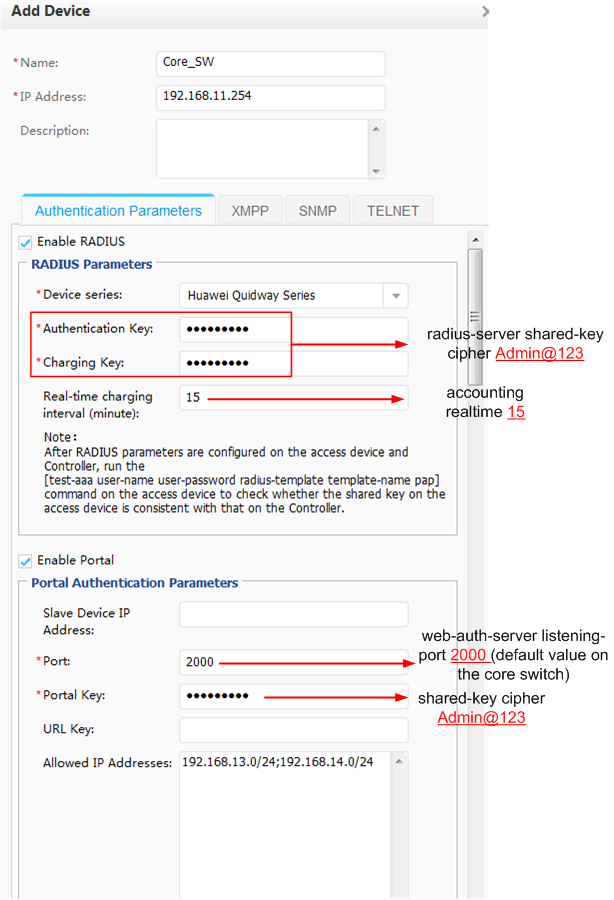
- Click XMPP.
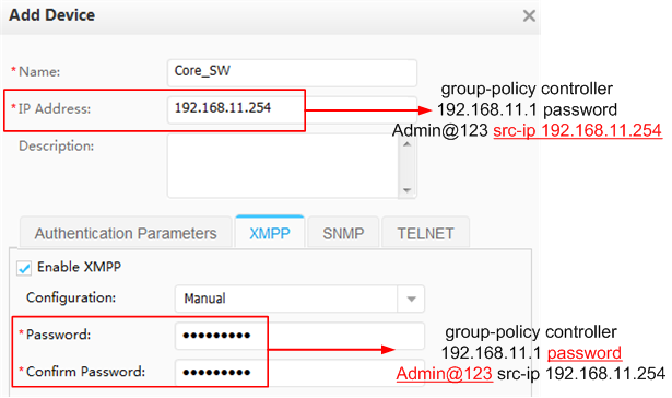
- Click OK. The switch's Status is
 and Synchronization Status is Success.
 - On the core switch, check the switch's communication status with the Agile Controller-Campus.
<coreswitch> display group-policy status
Controller IP address: 192.168.11.1
Controller port: 5222
Backup controller IP address: -
Backup controller port: -
Source IP address: 192.168.11.254
State: working
Connected controller: master
Device protocol version: 1
Controller protocol version: 1
- Choose .
- Configure security groups Employee_Group and Email_Server to indicate users and resources, respectively.
- Choose .
- Click Add and create Employee_Group.
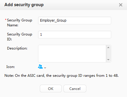
- Repeat the preceding step to create the security group Email_Server.
- Click
 next to Email_Server and bind IP addresses of email servers.
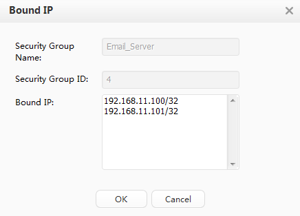
- Click Global Deployment to deploy the security groups on the entire network.
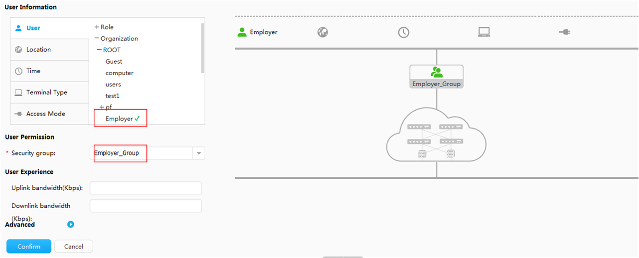
- Use fast authorization to authorize the security group Employee_Group to the employee department. Employees are mapped to the security group Employee_Group after being authenticated.
- Choose .
- Map the employee department to Employee_Group and click OK.
- Configure an access control policy to allow Employee_Group to access Email_Server.
- Choose .
- Click Add.
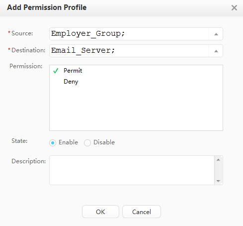
- Click OK and Global Deployment.
After the access control policy is successfully deployed, you can run the following commands on the core switch to view deployment information.
- display ucl-group all: displays security groups.
- display acl all: displays access control policies.
- Add the core switch.
- Save the configuration of Core_SW.
Choose . Click
 corresponding to Core_SW to save the configuration.
 Saving the configuration is similar to running the save command on the device, which saves all the device configurations (including security groups, access right control policies, and QoS policies deployed on the controller) to the configuration file.
If security groups, access right control policies, and QoS policies are saved to the device's configuration file, these configurations can be directly restored from the configuration file after the device restarts, and do not need to be requested from the controller. Otherwise, user authentication fails after the device restarts because security groups, access right control policies, and QoS policies are not deployed on the device.
- Verify the configuration.
Users using accounts in the employee department can access email servers after passing 802.1X or Portal authentication regardless of their access locations.
Configuration Files
Configuration file of the core switch
#
sysname coreswitch
#
vlan batch 11 to 14
#
wlan ac-global carrier id other ac id 1
#
group-policy controller 192.168.11.1 password %^%#(K2]5P#C6'97.pR(gFv$K$KbGYN}R1Y76~K^;AP&%^%# src-ip 192.168.11.254
#
dhcp enable
#
radius-server template policy
 radius-server shared-key cipher %^%#teXm2B&.1O0:cj$OWPq7@!Y\!%}dC3Br>p,}l\L.%^%#
 radius-server authentication 192.168.11.1 1812 weight 80
 radius-server accounting 192.168.11.1 1813 weight 80
#
url-template name huawei
 url http://192.168.11.1:8080/portal
#
web-auth-server policy
 server-ip 192.168.11.1
 port 50200
 shared-key cipher %^%#SQn,Cr"c;M&{#(R^:;P3F_H$3f3sr$C9%*G7R|u3%^%#
 url-template huawei
#
aaa
 authentication-scheme auth
  authentication-mode radius
 accounting-scheme acco
  accounting-mode radius
  accounting realtime 15
 domain default
  authentication-scheme auth
  accounting-scheme acco
  radius-server policy
#
interface Vlanif11
 ip address 192.168.11.254 255.255.255.0
#
interface Vlanif12
 ip address 192.168.12.254 255.255.255.0
 dhcp select interface
#
interface Vlanif13
 ip address 192.168.13.254 255.255.255.0
 dhcp select interface
 dhcp server dns-list 192.168.11.200
#
interface Vlanif14
 ip address 192.168.14.254 255.255.255.0
 dhcp select interface
 dhcp server dns-list 192.168.11.200
#
interface GigabitEthernet1/0/11
 port link-type trunk
 port trunk allow-pass vlan 11
#
interface GigabitEthernet1/0/12
 port link-type trunk
 port trunk allow-pass vlan 12 14
 domain name default force
 authentication dot1x portal
 web-auth-server policy direct
 dot1x authentication-method eap
#
interface Wlan-Ess32
 port trunk allow-pass vlan 13
 domain name default force
 authentication portal
 web-auth-server policy direct
#
interface Wlan-Ess33
 port trunk allow-pass vlan 13
 domain name default force
 authentication dot1x
 dot1x authentication-method eap
#
authentication free-rule 1 destination ip 192.168.11.200 mask 255.255.255.0 source ip any
authentication free-rule 2 source vlan 12
#
capwap source interface vlanif12
#
wlan
 ap-region id 10
 ap id 1 type-id 28 mac dcd2-fc04-b4c0
  region-id 10
 wmm-profile name wmm id 1
 traffic-profile name traffic id 1
 security-profile name portal_security id 32
 security-profile name dot1x_security id 33
  security-policy wpa2
 service-set name portal_test id 32
  forward-mode tunnel
  wlan-ess 32
  ssid portal_test
  traffic-profile id 1
  security-profile id 32
  service-vlan 13
 service-set name dot1x_test id 33
  forward-mode tunnel
  wlan-ess 33
  ssid dot1x_test
  traffic-profile id 1
  security-profile id 33
  service-vlan 13
 radio-profile name radio id 31
  wmm-profile id 1
 ap 1 radio 0
  radio-profile id 31
  service-set id 32 wlan 1
  service-set id 33 wlan 2
 wlan work-group default         //This configuration will be displayed on modular switches but not on fixed switches.
#
return
Configuration file of the access switch
#
sysname l2switch
#
vlan batch 12 14
#
l2protocol-tunnel user-defined-protocol 802.1x protocol-mac 0180-c200-0003 group-mac 0100-0000-0002
#
interface GigabitEthernet0/0/1
 port link-type trunk
 port trunk allow-pass vlan 12 14
 l2protocol-tunnel user-defined-protocol 802.1x enable
#
interface GigabitEthernet0/0/3
 port link-type access
 port default vlan 14
 l2protocol-tunnel user-defined-protocol 802.1x enable
#
interface GigabitEthernet0/0/5
 port link-type access
 port default vlan 12
 l2protocol-tunnel user-defined-protocol 802.1x enable
#
return