Example for Deploying the Free Mobility Function for Users' Physical Location Change (V200R009 and later versions)
Free Mobility Overview
In an enterprise network, different network access policies can be deployed for users on access devices to meet different network access requirements. The application of mobile office and BYOD technologies brings frequent changes of users' physical locations and IP addresses. Therefore, the original network control solution based on physical ports and IP addresses cannot ensure consistency of network access experience. For example, the network access policy of a user does not change when the user's physical location changes.
The free mobility solution allows a user to obtain the same network access policy regardless of the user's location and IP address changes.
The switches must be associated with the Agile Controller-Campus in the free mobility solution. An administrator only needs to uniformly deploy network access policies on the Agile Controller-Campus for users, and deliver the policies to all associated switches. Then, a user can obtain the same access policy no matter how the user's physical location and IP address change.
Networking Requirements
Employees in an enterprise connect to the network in wired and wireless modes and are authenticated using 802.1X or Portal authentication.
The employees do not work in fixed locations and want to obtain the same rights after being authenticated regardless of their access locations.
Requirement Analysis
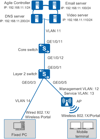
As shown in Figure 1, the agile core switch coreswitch functions as the authentication point and the access switch is a common switch.
You can configure 802.1X authentication and Portal authentication on the core switch so that wired and wireless users can connect to the network after being authenticated by the core switch.
The employees do not work in fixed locations and want to obtain the same rights after being authenticated regardless of their access locations.
Configuration Notes
- Free mobility is supported only in NAC unified mode.
- In this example, the Agile Controller-Campus runs V100R003C00.
When the controller delivers a UCL group name that is not supported by the switch, for example, this group name contains Chinese characters or special characters, the switch cannot parse the group name. A UCL group name that can be supported by the switch must be consistent with the value of group-name in the ucl-group group-index [ name group-name ] command, cannot be -, --, a, an, or any, and cannot contain any of the following characters: / \ : * ? " < > | @ ' %. Therefore, when configuring a UCL group name on the controller, do not use Chinese characters or special characters.
If the switch has been associated with an Agile Controller-Campus and has free mobility configured, perform the following steps to delete historical data and reconfigure the core switch.
- Run the undo group-policy controller command in the system view to disable free mobility and disconnect the switch from the Agile Controller-Campus.
- Run the undo acl all command to delete the access control policy.
- Run the undo ucl-group ip all command to delete IP addresses bound to security groups.
- Run the undo ucl-group all command to delete security groups.
- Return to the user view and run the save command. The system automatically deletes the configured version number.
Data Plan
Item |
Data |
Description |
|
|---|---|---|---|
VLAN plan |
ID: 11 VLANIF11 IP address: 192.168.11.254/24 |
The core switch uses this VLAN to communicate with the Agile Controller-Campus. |
|
ID: 12 VLANIF12 IP address: 192.168.12.254/24 |
The core switch uses this VLAN to manage APs. |
||
ID: 13 VLANIF13 IP address: 192.168.13.254/24 |
The core switch uses this VLAN to provide wireless access services. |
||
ID: 14 VLANIF14 IP address: 192.168.14.254/24 |
The core switch uses this VLAN to provide wired access services. |
||
Core switch (coreswitch) |
Interface number: GE1/0/11 IDs of allowed VLANs: 11 |
IDs of allowed VLANs: 11, 12, 13, and 14 |
|
Interface number: GE1/0/12 IDs of allowed VLANs: 12, 14 |
This interface allows packets from the wired access service VLAN and APs' management VLAN to pass through. |
||
Access switch |
Interface number: GE0/0/1 IDs of allowed VLANs: 12, 14 |
This interface connects to GE1/0/12 on the core switch (coreswitch). |
|
Interface number: GE0/0/3 IDs of allowed VLANs: 14 |
This interface provides wired access and allows packets from the wired access service VLAN to pass through. |
||
Interface number: GE0/0/5 IDs of allowed VLANs: 12 |
This interface provides wireless access and allows packets from the APs' management VLAN to pass through. |
||
Server |
Agile Controller-Campus: 192.168.11.1 |
The Service Manager (SM) and Service Controller (SC) are installed on the same server. The SC functions as both the RADIUS server and Portal server. |
|
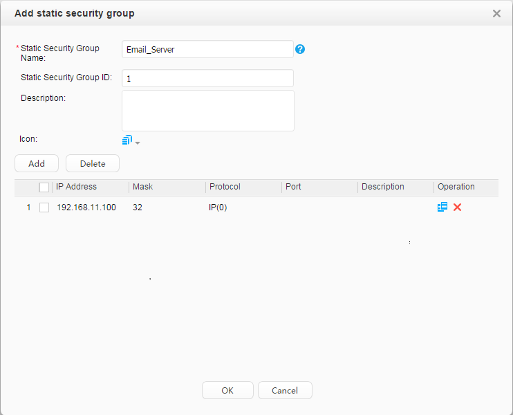
Email server: 192.168.11.100 |
- |
||
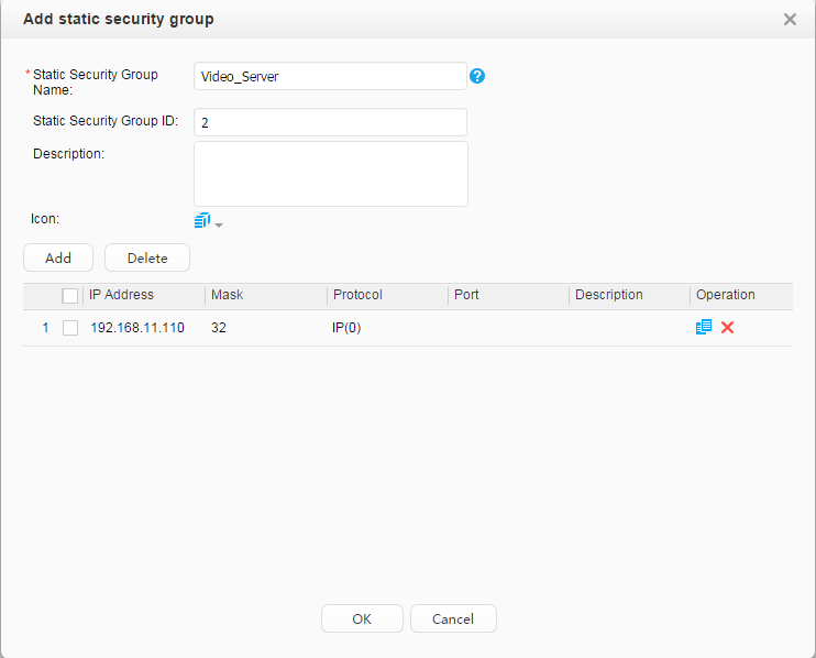
Video server: 192.168.11.110 |
- |
||
DNS server: 192.168.11.200 |
– |
||
Item |
Data |
Description |
|---|---|---|
Core switch (coreswitch) |
RADIUS authentication server:
|
|
RADIUS accounting server:
|
||
Portal server:
|
||
XMPP password: Admin@123 |
The configuration is the same as that on the Agile Controller-Campus. |
|
Agile Controller-Campus |
Core switch's IP address: 192.168.11.254 |
This IP address is the IP address of VLANIF 11. |
RADIUS parameters:
|
The configuration is the same as that on the core switch. |
|
Portal parameters:
|
||
XMPP password: Admin@123 |
The configuration is the same as that on the core switch. |
|
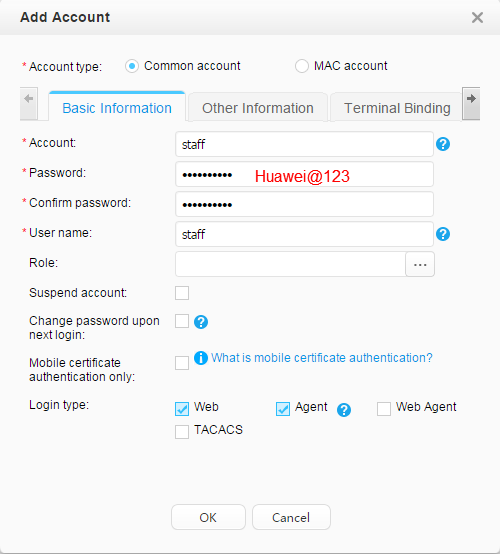
Account: Employees:
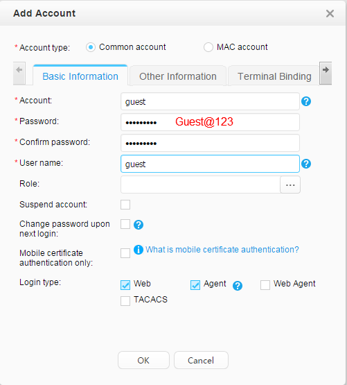
Guests:
|
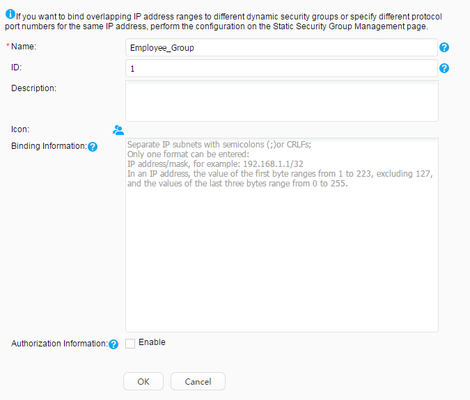
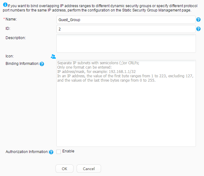
Use fast authorization to authorize the security group Employee_Group to the staff. Use fast authorization to authorize the security group Guest_Group to the guest. |
|
Security group: Employee_Group Guest_Group Email server: 192.168.11.100 Video server: 192.168.11.110 |
– |
|
Pre-authentication domain |
DNS server |
Employees can send domain names to the DNS server for resolution before being authenticated. |
Post-authentication domain |
Email servers, video server |
After passing authentication, employees can access the mail server and video server. You can improve bandwidth for employees to access the video server. After passing authentication, guests cannot access the mail server and can only access the video server. You can reduce bandwidth for guests to access the video server. |
Procedure
- Configure the access switch.

In this example, an access switch exists between users and the core switch functioning as the authentication point, and transparently transmits packets. To ensure that users can pass 802.1X authentication, configure the access switch to transparently transmit 802.1X packets (EAP packets in this example because EAP mode is used).
<HUAWEI> system-view
[HUAWEI] sysname l2switch
[l2switch] l2protocol-tunnel user-defined-protocol 802.1x protocol-mac 0180-c200-0003 group-mac 0100-0000-0002
[l2switch] vlan batch 12 14
[l2switch] interface gigabitEthernet 0/0/1
[l2switch-GigabitEthernet0/0/1] port link-type trunk
[l2switch-GigabitEthernet0/0/1] port trunk allow-pass vlan 12 14
[l2switch-GigabitEthernet0/0/1] l2protocol-tunnel user-defined-protocol 802.1x enable
[l2switch-GigabitEthernet0/0/1] bpdu enable
[l2switch-GigabitEthernet0/0/1] quit
[l2switch] interface gigabitEthernet 0/0/3    //Wired access interface
[l2switch-GigabitEthernet0/0/3] port link-type access
[l2switch-GigabitEthernet0/0/3] port default vlan 14
[l2switch-GigabitEthernet0/0/3] l2protocol-tunnel user-defined-protocol 802.1x enable
[l2switch-GigabitEthernet0/0/3] bpdu enable
[l2switch-GigabitEthernet0/0/3] quit
[l2switch] interface gigabitEthernet 0/0/5    //Wireless access interface
[l2switch-GigabitEthernet0/0/5] port link-type access
[l2switch-GigabitEthernet0/0/5] port default vlan 12
[l2switch-GigabitEthernet0/0/5] l2protocol-tunnel user-defined-protocol 802.1x enable
[l2switch-GigabitEthernet0/0/5] bpdu enable
[l2switch-GigabitEthernet0/0/5] quit
- Configure the core switch.
- Switch the NAC configuration mode to unified mode.
You must switch the NAC configuration mode to unified mode on a device with the free mobility function configured. When the switchover occurs, the device will reboot automatically.
<HUAWEI> system-view
[HUAWEI] sysname coreswitch
[coreswitch] authentication unified-mode
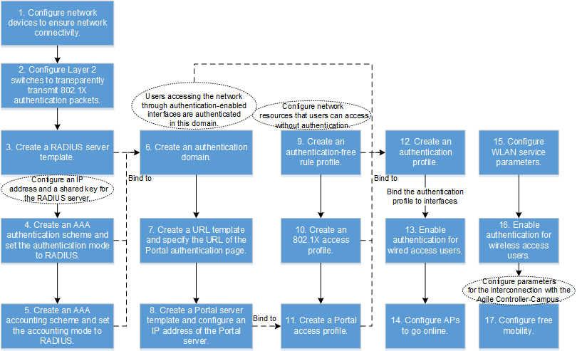
- Configure NAC.
- Configure the 802.1X access profile d1.
By default, an 802.1X access profile uses the EAP authentication mode. Ensure that the RADIUS server supports EAP; otherwise, the server cannot process 802.1X authentication request packets.
[coreswitch] dot1x-access-profile name d1
[coreswitch-dot1x-access-profile-d1] quit
Configure the Portal access profile web1.
[coreswitch] portal-access-profile name web1
[coreswitch-portal-acces-profile-web1] web-auth-server policy direct   //Configure Layer 2 Portal authentication.
[coreswitch-portal-acces-profile-web1] quit
Configure the authentication-free rule profile default_free_rule.
[coreswitch] free-rule-template name default_free_rule
[coreswitch-free-rule-default_free_rule] free-rule 1 destination ip 192.168.11.200 mask 24 source ip any    //Ensure that terminal can access the DNS server before being authenticated.
[coreswitch-free-rule-default_free_rule] free-rule 2 source vlan 12    //Ensure that APs can go online.
[coreswitch-free-rule-default_free_rule] quit
Configure the authentication profile p1 for 802.1X + Portal combined authentication.
[coreswitch] authentication-profile name p1
[coreswitch-authen-profile-p1] dot1x-access-profile d1    //Bind the 802.1X access profile d1.
[coreswitch-authen-profile-p1] portal-access-profile web1    //Bind the Portal access profile web1.
[coreswitch-authen-profile-p1] access-domain default force    //Configure the domain default as the forcible authentication domain for users who go online through this interface.
[coreswitch-authen-profile-p1] quit
Configure the authentication profile p_dot1x for 802.1X authentication.
[coreswitch] authentication-profile name p_dot1x
[coreswitch-authen-profile-p_dot1x] dot1x-access-profile d1    //Bind the 802.1X access profile d1.
[coreswitch-authen-profile-p_dot1x] free-rule-template default_free_rule    //Bind the authentication-free rule profile default_free_rule.
[coreswitch-authen-profile-p_dot1x] access-domain default force    //Configure the domain default as the forcible authentication domain for users who go online through this interface.
[coreswitch-authen-profile-p_dot1x] quit
Configure the authentication profile p_portal for Portal authentication.
[coreswitch] authentication-profile name p_portal
[coreswitch-authen-profile-p_portal] portal-access-profile web1    //Bind the Portal access profile web1.
[coreswitch-authen-profile-p_portal] free-rule-template default_free_rule    //Bind the authentication-free rule profile default_free_rule.
[coreswitch-authen-profile-p_portal] access-domain default force    //Configure the domain default as the forcible authentication domain for users who go online through this interface.
[coreswitch-authen-profile-p_portal] quit
- Switch the NAC configuration mode to unified mode.
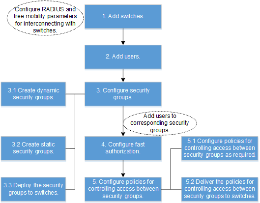
- Configure the Agile Controller-Campus.
- Add the core switch.
- Choose and click Add.
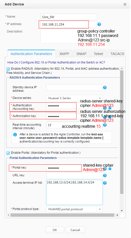
- Click XMPP.
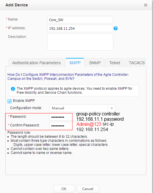
- Click OK. The switch's Status is
 and Synchronization Status is Success.
 - On the core switch, check the switch's communication status with the Agile Controller-Campus.
<coreswitch> display group-policy status
Controller IP address: 192.168.11.1
Controller port: 5222
Backup controller IP address: -
Backup controller port: -
Source IP address: 192.168.11.254
State: working
Connected controller: master
Device protocol version: 1
Controller protocol version: 1
- Choose and click Add.
- Create the staff and guest accounts.
- Choose .
- Click Add to create the staff account.
- Click Add to create the guest account.
- Configure the employee group and guest group, and security groups mail server and video server.
- Choose .
- Click Add and create Employee_Group.
- Click Add and create Guest_Group.
- Choose , click Add and create Email_Server.
- Click Add and create Video_Server.
- Click Global Deployment to deploy the security groups on the entire network.
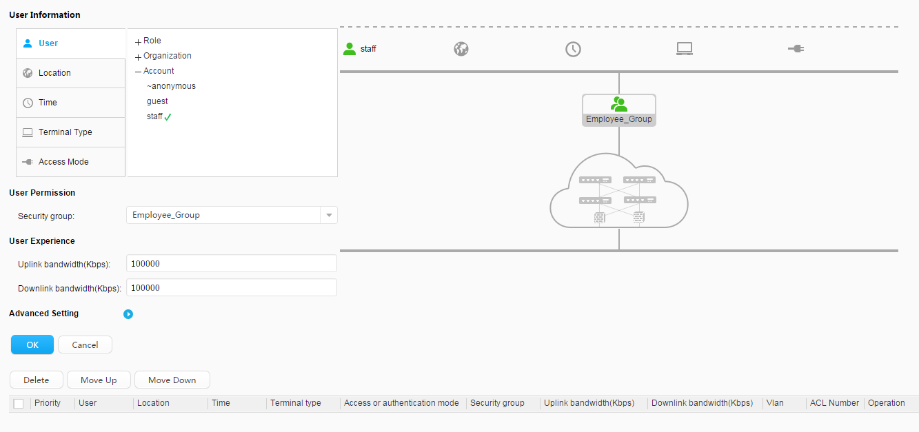
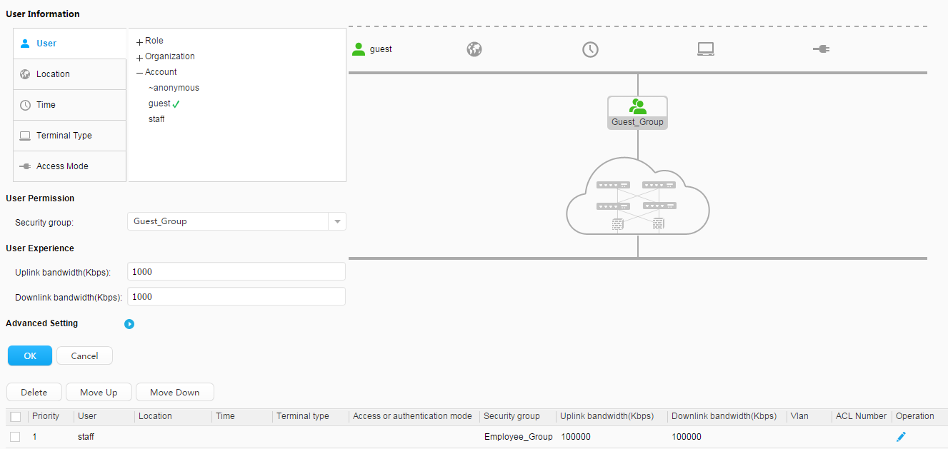
- Authorize the employee group to employees and guest group to guests. After passing authentication, employees are added to the employee group and guests are added to the guest group.
- Choose .
- Map employees to Employee group, set bandwidth, and click OK.
- Map guests to Guest group, set bandwidth, and click OK.
- Configure an access control policy to allow the employee group to access the mail and video servers and allow the guest group to access only the video server.
The default policy configuration mode is customized group. If there is no customized group, add a customized group on the device management page first (choose ). You can also change the policy configuration mode to all devices (choose ).
- Choose .
- Click Add.
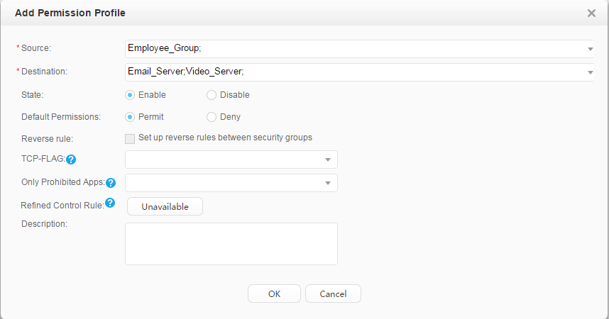
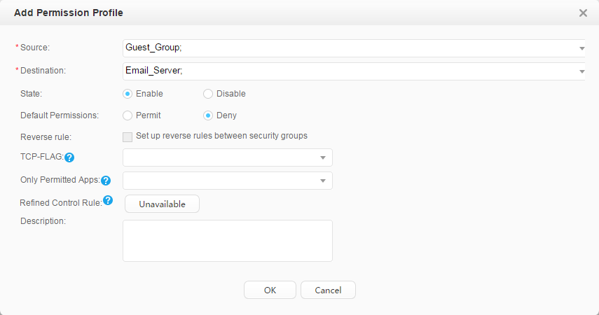
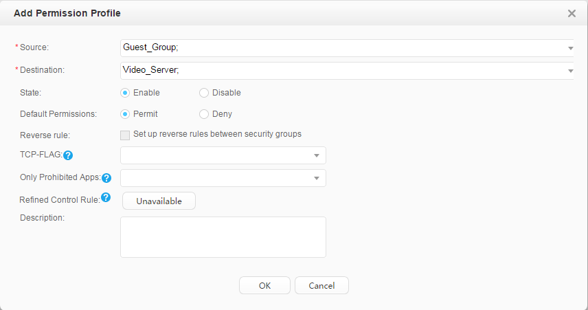
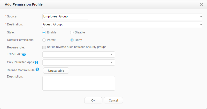
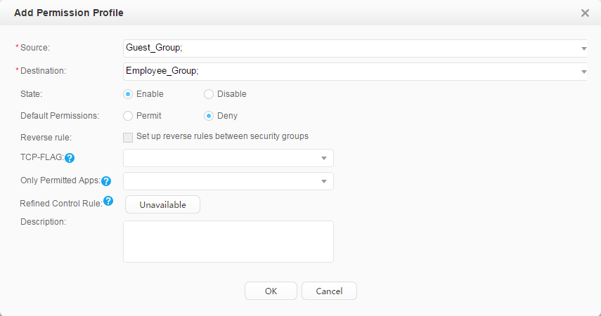
- Click OK and Global Deployment.
After the access control policy is successfully deployed, you can run the following commands on the core switch to view deployment information.
- display ucl-group all: displays security groups.
- display acl all: displays the access control policy.
- Add the core switch.
- Save the configuration of Core_SW.
Choose . Click
 corresponding to Core_SW to save the configuration.
 Saving the configuration is similar to running the save command on the device, which saves all the device configurations (including security groups, access right control policies, and QoS policies deployed on the controller) to the configuration file.
If security groups, access right control policies, and QoS policies are saved to the device's configuration file, these configurations can be directly restored from the configuration file after the device restarts, and do not need to be requested from the controller. Otherwise, user authentication fails after the device restarts because security groups, access right control policies, and QoS policies are not deployed on the device.
- Verify the configuration.
After passing 802.1X or Portal authentication anywhere, the employees can access the mail and video servers, and the videos can be smoothly played.
After passing 802.1X or Portal authentication anywhere, the guests cannot access the mail server but can only access the video server, and the videos may freeze.
Configuration Files
Core switch configuration file
#
sysname coreswitch
#
vlan batch 11 to 14
#
authentication-profile name p1
 dot1x-access-profile d1
 portal-access-profile web1
 access-domain default force
authentication-profile name p_dot1x
 dot1x-access-profile d1
 free-rule-template default_free_rule
 access-domain default force
authentication-profile name p_portal
 portal-access-profile web1
 free-rule-template default_free_rule
 access-domain default force
#
group-policy controller 192.168.11.1 password %^%#(K2]5P#C6'97.pR(gFv$K$KbGYN}R1Y76~K^;AP&%^%# src-ip 192.168.11.254
#
dhcp enable
#
radius-server template policy
 radius-server shared-key cipher %^%#teXm2B&.1O0:cj$OWPq7@!Y\!%}dC3Br>p,}l\L.%^%#
 radius-server authentication 192.168.11.1 1812 weight 80
 radius-server accounting 192.168.11.1 1813 weight 80
#
radius-server authorization 192.168.11.1 shared-key cipher %^%#FKIlCKv=f(AgM-G~W"}G.C\%;b'3A/zz-EJV;vi*%^%#
#
free-rule-template name default_free_rule
 free-rule 1 destination ip 192.168.11.200 mask 255.255.255.0 source ip any
 free-rule 2 source vlan 12
#
url-template name huawei
 url http://192.168.11.1:8080/portal
#
web-auth-server policy
 server-ip 192.168.11.1
 port 50200
 shared-key cipher %^%#SQn,Cr"c;M&{#(R^:;P3F_H$3f3sr$C9%*G7R|u3%^%#
 url-template huawei
#
portal-access-profile name web1
 web-auth-server policy direct
#
aaa
 authentication-scheme auth
  authentication-mode radius
 accounting-scheme acco
  accounting-mode radius
  accounting realtime 15
 domain default
  authentication-scheme auth
  accounting-scheme acco
  radius-server policy
#
interface Vlanif11
 ip address 192.168.11.254 255.255.255.0
#
interface Vlanif12
 ip address 192.168.12.254 255.255.255.0
 dhcp select interface
#
interface Vlanif13
 ip address 192.168.13.254 255.255.255.0
 dhcp select interface
 dhcp server dns-list 192.168.11.200
#
interface Vlanif14
 ip address 192.168.14.254 255.255.255.0
 dhcp select interface
 dhcp server dns-list 192.168.11.200
#
interface GigabitEthernet1/0/11
 port link-type trunk
 port trunk allow-pass vlan 11
#
interface GigabitEthernet1/0/12
 port link-type trunk
 port trunk allow-pass vlan 12 14
 authentication-profile p1
#
capwap source interface vlanif12
#
wlan
 security-profile name wlan-security1
 security-profile name wlan-security2
  security wpa2 dot1x aes
 ssid-profile name dot1x_test
  ssid dot1x_test
 ssid-profile name portal_test
  ssid portal_test
 vap-profile name dot1x_test
  forward-mode tunnel
  service-vlan vlan-id 13
  ssid-profile dot1x_test
  security-profile wlan-security2
  authentication-profile p_dot1x
 vap-profile name portal_test
  forward-mode tunnel
  service-vlan vlan-id 13
  ssid-profile portal_test
  security-profile wlan-security1
  authentication-profile p_portal
 regulatory-domain-profile name domain1
 ap-group name ap-group1
  regulatory-domain-profile domain1
  radio 0
   vap-profile dot1x_test wlan 1
   vap-profile portal_test wlan 2
  radio 1
   vap-profile dot1x_test wlan 1
   vap-profile portal_test wlan 2
  radio 2
   vap-profile dot1x_test wlan 1
   vap-profile portal_test wlan 2
 ap-id 0 ap-mac 60de-4476-e360
  ap-name area_1
  ap-group ap-group1
 wlan work-group default
#
dot1x-access-profile name d1
#
return
Configuration file of the access switch
#
sysname l2switch
#
vlan batch 12 14
#
l2protocol-tunnel user-defined-protocol 802.1x protocol-mac 0180-c200-0003 group-mac 0100-0000-0002
#
interface GigabitEthernet0/0/1
 port link-type trunk
 port trunk allow-pass vlan 12 14
 l2protocol-tunnel user-defined-protocol 802.1x enable
#
interface GigabitEthernet0/0/3
 port link-type access
 port default vlan 14
 l2protocol-tunnel user-defined-protocol 802.1x enable
#
interface GigabitEthernet0/0/5
 port link-type access
 port default vlan 12
 l2protocol-tunnel user-defined-protocol 802.1x enable
#
return
Card or Switch Where the Authentication Control Point Can Be Deployed
Switch Version |
Card or Switch Where the Authentication Control Point Can Be Deployed |
|---|---|
V200R009C00 |
Only the S5720-HI supports V200R011C00. |
V200R010C00 |
|
V200R011C00, V200R011C10 |
|
V200R012C00 and later versions |
|