Example for Configuring a Layer 2 Switch to Work with a Firewall for Internet Access
Layer 2 Switch
Layer 2 switches perform only Layer 2 forwarding instead of Layer 3 forwarding. That is, Layer 2 switches support only Layer 2 switches instead of Layer 3 features such as routing.
Layer 2 switches are typically deployed at the access layer and cannot function as gateways of users.
Configuration Notes
Switch configurations used in this example apply to all versions of all S series switches.
This example uses firewall configurations of USG6650 V500R001C60. For other firewall configurations, see the corresponding documentation.
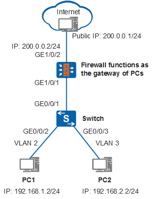
Networking Requirements
In Figure 1, a company has multiple departments that belong to different network segments, and each department needs to access the Internet. It is required that users access the Internet through the Layer 2 switch and firewall and that the firewall function as the gateway of users.
Configuration Roadmap
The configuration roadmap is as follows:
Configure interface-based VLAN assignment on the switch for Layer 2 forwarding.
Configure the firewall as the gateway of users to implement Layer 3 forwarding across network segments through sub-interfaces or VLANIF interfaces.
Configure the firewall as the DHCP server to assign IP addresses to users.
Configure a security interzone policy for the firewall so that packets of different zones can be forwarded.
Configure the PAT function on the firewall to enable intranet users to access the Internet.
Procedure
- Configure the switch.
# Configure the interfaces connected to users.
<HUAWEI> system-view
[HUAWEI] sysname Switch
[Switch] vlan batch 2 3
[Switch] interface gigabitethernet 0/0/2
[Switch-GigabitEthernet0/0/2] port link-type access   //Set the link type of the interface to access.
[Switch-GigabitEthernet0/0/2] port default vlan 2   //Add the interface to VLAN 2.
[Switch-GigabitEthernet0/0/2] quit
[Switch] interface gigabitethernet 0/0/3
[Switch-GigabitEthernet0/0/3] port link-type access
[Switch-GigabitEthernet0/0/3] port default vlan 3
[Switch-GigabitEthernet0/0/3] quit
# Configure the interface connected to the firewall.
[Switch] interface gigabitethernet 0/0/1
[Switch-GigabitEthernet0/0/1] port link-type trunk
[Switch-GigabitEthernet0/0/1] port trunk allow-pass vlan 2 3   //Configure the interface as a trunk interface to transparently transmit packets from VLAN 2 and VLAN 3.
[Switch-GigabitEthernet0/0/1] quit
- Configure the firewall.
Two methods are available to configure a firewall: one is to configure sub-interfaces and the other is to configure VLANIF interfaces.
Configure the firewall to terminate VLAN tags through sub-interfaces to implement Layer 3 forwarding across network segments.
# Configure sub-interfaces for VLAN tag termination.
<USG6600> system-view
[USG6600] interface gigabitethernet 1/0/1.1
[USG6600-GigabitEthernet1/0/1.1] vlan-type dot1q 2
[USG6600-GigabitEthernet1/0/1.1] ip address 192.168.1.1 24
[USG6600-GigabitEthernet1/0/1.1] quit
[USG6600] interface gigabitethernet 1/0/1.2
[USG6600-GigabitEthernet1/0/1.2] vlan-type dot1q 3
[USG6600-GigabitEthernet1/0/1.2] ip address 192.168.2.1 24
[USG6600-GigabitEthernet1/0/1.2] quit
# Configure the DHCP function to assign IP addresses to intranet users and specify the DNS server address.
[USG6600] dhcp enable
[USG6600] interface gigabitethernet 1/0/1.1
[USG6600-GigabitEthernet1/0/1.1] dhcp select interface   //Enable the DHCP server function on the interface and configure it to use an interface address pool.
[USG6600-GigabitEthernet1/0/1.1] dhcp server dns-list 114.114.114.114 223.5.5.5   //The configured DNS-list 114.114.114.114 is a public DNS server address, which is the same for carriers. In practice, the DNS-list address needs to be configured based on the DNS assigned to a carrier.[USG6600-GigabitEthernet1/0/1.1] quit
[USG6600] interface gigabitethernet 1/0/1.2
[USG6600-GigabitEthernet1/0/1.2] dhcp select interface
[USG6600-GigabitEthernet1/0/1.2] dhcp server dns-list 114.114.114.114 223.5.5.5
[USG6600-GigabitEthernet1/0/1.2] quit
# Configure a public network interface IP address and a static route.
[USG6600] interface gigabitethernet 1/0/2
[USG6600-GigabitEthernet1/0/2] ip address 200.0.0.2 255.255.255.0   //Configure an IP address 200.0.0.2 for GE0/0/2 connected to the public network.
[USG6600-GigabitEthernet1/0/2] quit
[USG6600] ip route-static 0.0.0.0 0.0.0.0 200.0.0.1   //Configure a static default route with the next hop pointing to the public IP address 200.0.0.1.
# Configure security zones.
[USG6600] firewall zone trust   //Configure a trust zone.
[USG6600-zone-trust] add interface gigabitethernet 1/0/1
[USG6600-zone-trust] add interface gigabitethernet 1/0/1.1
[USG6600-zone-trust] add interface gigabitethernet 1/0/1.2
[USG6600-zone-trust] quit
[USG6600] firewall zone untrust   //Configure an untrust zone.
[USG6600-zone-untrust] add interface gigabitethernet 1/0/2
[USG6600-zone-untrust] quit
# Configure a security policy to allow inter-zone access.[USG6600] security-policy [USG6600-policy-security] rule name policy1 [USG6600-policy-security-rule-policy1] source-zone trust [USG6600-policy-security-rule-policy1] destination-zone untrust [USG6600-policy-security-rule-policy1] source-address 192.168.0.0 mask 255.255.0.0 [USG6600-policy-security-rule-policy1] action permit [USG6600-policy-security-rule-policy1] quit [USG6600-policy-security] quit
# Configure a PAT address pool to allow interface address translation.[USG6600] nat address-group addressgroup1 [USG6600-address-group-addressgroup1] mode pat [USG6600-address-group-addressgroup1] route enable [USG6600-address-group-addressgroup1] section 0 200.0.0.2 200.0.0.2 //Translated public IP address [USG6600-address-group-addressgroup1] quit# Configure a PAT policy so that source IP addresses are automatically translated when devices on a specified network segment of an internal network access the Internet.[USG6600] nat-policy [USG6600-policy-nat] rule name policy_nat1 [USG6600-policy-nat-rule-policy_nat1] source-zone trust [USG6600-policy-nat-rule-policy_nat1] destination-zone untrust [USG6600-policy-nat-rule-policy_nat1] source-address 192.168.0.0 mask 255.255.0.0 //Source IP address that can be translated using PAT [USG6600-policy-nat-rule-policy_nat1] action nat address-group addressgroup1 [USG6600-policy-nat-rule-policy_nat1] quit [USG6600-policy-nat] quit [USG6600] quitConfigure VLANIF interfaces on the firewall to implement Layer 3 forwarding across network segments.
# Configure VLANIF interfaces.
<USG6600> system-view
[USG6600] vlan batch 2 3
[USG6600] interface gigabitethernet 1/0/1
[USG6600-GigabitEthernet1/0/1] portswitch   //Change the Ethernet interface from Layer 3 mode to Layer 2 mode. If it has worked in Layer 2 mode, skip this step.
[USG6600-GigabitEthernet1/0/1] port link-type hybrid
[USG6600-GigabitEthernet1/0/1] port hybrid tagged vlan 2 to 3
[USG6600-GigabitEthernet1/0/1] quit
[USG6600] interface vlanif 2
[USG6600-Vlanif2] ip address 192.168.1.1 24   //Configure the IP address of VLANIF2 as the gateway address of PC1.
[USG6600-Vlanif2] quit
[USG6600] interface vlanif 3
[USG6600-Vlanif3] ip address 192.168.2.1 24   //Configure the IP address of VLANIF3 as the gateway address of PC2.
[USG6600-Vlanif3] quit
# Configure the DHCP and DNS functions.
[USG6600] dhcp enable
[USG6600] interface vlanif 2
[USG6600-Vlanif2] dhcp select interface
[USG6600-Vlanif2] dhcp server dns-list 114.114.114.114 223.5.5.5   //The configured DNS-list 114.114.114.114 is a public DNS server address, which is the same for carriers. In practice, the DNS-list address needs to be configured based on the DNS assigned to a carrier.[USG6600-Vlanif2] quit
[USG6600] interface vlanif 3
[USG6600-Vlanif3] dhcp select interface
[USG6600-Vlanif3] dhcp server dns-list 114.114.114.114 223.5.5.5
[USG6600-Vlanif3] quit
# Configure a public network interface IP address and a static route.
[USG6600] interface gigabitethernet 1/0/2
[USG6600-GigabitEthernet1/0/2] ip address 200.0.0.2 255.255.255.0
[USG6600-GigabitEthernet1/0/2] quit
[USG6600] ip route-static 0.0.0.0 0.0.0.0 200.0.0.1   //Configure a static default route with the next hop pointing to the public IP address 200.0.0.1.
# Configure security zones.
[USG6600] firewall zone trust
[USG6600-zone-trust] add interface gigabitethernet 1/0/1
[USG6600-zone-trust] add interface vlanif 2
[USG6600-zone-trust] add interface vlanif 3
[USG6600-zone-trust] quit
[USG6600] firewall zone untrust
[USG6600-zone-untrust] add interface gigabitethernet 1/0/2
[USG6600-zone-untrust] quit
# Configure a security policy to allow inter-zone access.[USG6600] security-policy [USG6600-policy-security] rule name policy1 [USG6600-policy-security-rule-policy1] source-zone trust [USG6600-policy-security-rule-policy1] destination-zone untrust [USG6600-policy-security-rule-policy1] source-address 192.168.0.0 mask 255.255.0.0 [USG6600-policy-security-rule-policy1] action permit [USG6600-policy-security-rule-policy1] quit [USG6600-policy-security] quit
# Configure a PAT address pool to allow interface address translation.[USG6600] nat address-group addressgroup1 [USG6600-address-group-addressgroup1] mode pat [USG6600-address-group-addressgroup1] route enable [USG6600-address-group-addressgroup1] section 0 200.0.0.2 200.0.0.2 //Translated public IP address [USG6600-address-group-addressgroup1] quit# Configure a PAT policy so that source IP addresses are automatically translated when devices on a specified network segment of an internal network access the Internet.[USG6600] nat-policy [USG6600-policy-nat] rule name policy_nat1 [USG6600-policy-nat-rule-policy_nat1] source-zone trust [USG6600-policy-nat-rule-policy_nat1] destination-zone untrust [USG6600-policy-nat-rule-policy_nat1] source-address 192.168.0.0 mask 255.255.0.0 //Source IP address that can be translated using PAT [USG6600-policy-nat-rule-policy_nat1] action nat address-group addressgroup1 [USG6600-policy-nat-rule-policy_nat1] quit [USG6600-policy-nat] quit [USG6600] quit
- Check the configuration.
Configure an IP address 192.168.1.2/24 and a gateway address 192.168.1.1 for PC1, and configure an IP address 192.168.2.2/24 and a gateway address 192.168.2.1 for PC2.
Configure an IP address 200.0.0.1/24 and a gateway address 200.0.0.2 for external network.
After the configurations are complete, PC1 and PC2 can ping the external network IP address 200.0.0.1/24 and access the Internet.
Configuration Files
- Switch configuration file
#
sysname Switch
#
vlan batch 2 to 3
#
interface GigabitEthernet0/0/1
 port link-type trunk
 port trunk allow-pass vlan 2 to 3
#
interface GigabitEthernet0/0/2
 port link-type access
 port default vlan 2
#
interface GigabitEthernet0/0/3
 port link-type access
 port default vlan 3
#
return
- USG configuration file (used when the firewall performs Layer
3 forwarding through sub-interfaces)
# interface GigabitEthernet1/0/1 # interface GigabitEthernet1/0/1.1 vlan-type dot1q 2 ip address 192.168.1.1 255.255.255.0 dhcp select interface dhcp server dns-list 114.114.114.114 223.5.5.5 # interface GigabitEthernet1/0/1.2 vlan-type dot1q 3 ip address 192.168.2.1 255.255.255.0 dhcp select interface dhcp server dns-list 114.114.114.114 223.5.5.5 # interface GigabitEthernet1/0/2 ip address 200.0.0.2 255.255.255.0 # firewall zone trust set priority 85 add interface GigabitEthernet1/0/1 add interface GigabitEthernet1/0/1.1 add interface GigabitEthernet1/0/1.2 # firewall zone untrust set priority 5 add interface GigabitEthernet1/0/2 # ip route-static 0.0.0.0 0.0.0.0 200.0.0.1 # nat address-group addressgroup1 0 mode pat route enable section 0 200.0.0.2 200.0.0.2 # security-policy rule name policy1 source-zone trust destination-zone untrust source-address 192.168.0.0 mask 255.255.0.0 action permit # nat-policy rule name policy_nat1 source-zone trust destination-zone untrust source-address 192.168.0.0 mask 255.255.0.0 action nat address-group addressgroup1 # return - USG configuration file (used when the firewall performs Layer
3 forwarding through VLANIF interfaces)
#
 vlan batch 2 to 3
#
interface Vlanif2
 ip address 192.168.1.1 255.255.255.0
 dhcp server dns-list 114.114.114.114 223.5.5.5
#
interface Vlanif3
 ip address 192.168.2.1 255.255.255.0
 dhcp select interface
 dhcp server dns-list 114.114.114.114 223.5.5.5
#
interface GigabitEthernet1/0/1
 portswitch
 port hybrid tagged vlan 2 to 3
#
interface GigabitEthernet1/0/2
 ip address 200.0.0.2 255.255.255.0
#
firewall zone trust
 set priority 85
 add interface GigabitEthernet1/0/1
 add interface Vlanif2
 add interface Vlanif3
#
firewall zone untrust
 set priority 5
 add interface GigabitEthernet1/0/2
#
 ip route-static 0.0.0.0 0.0.0.0 200.0.0.1
#
nat address-group addressgroup1 0
 mode pat
 route enable
 section 0 200.0.0.2 200.0.0.2
#
security-policy
 rule name policy1
  source-zone trust
  destination-zone untrust
  source-address 192.168.0.0 mask 255.255.0.0
  action permit
#
nat-policy
 rule name policy_nat1
  source-zone trust
  destination-zone untrust
  source-address 192.168.0.0 mask 255.255.0.0
  action nat address-group addressgroup1
#
return