Basic Concepts of CFM
CFM Versions
Ethernet CFM, a network-level Ethernet OAM mechanism, supports functions including end-to-end connectivity fault detection, fault advertisement, fault acknowledgement, and fault locations. CFM monitors network connectivity and pinpoints connectivity faults. It is used with protection switching techniques to make networks more reliable.
Huawei devices implement IEEE 802.1ag/Draft 7 and Std 802.1ag-2007. Table 1 lists support for 802.1ag/Draft 7 and Std 802.1ag-2007 on Huawei devices.
Function |
802.1ag/Draft 7 |
Std 802.1ag-2007 |
Difference |
|---|---|---|---|
Maintenance domain (MD) |
Supported |
Supported |
None |
Default MD |
Not supported |
Supported |
N/A |
Maintenance association (MA) |
Supported |
Supported |
None |
Maintenance association endpoint (MEP) |
Supported |
Supported |
None |
Maintenance association intermediate point (MIP) |
Supported |
Supported |
Both 802.1ag versions support the same types of MIP creation rules: default, explicit, and none. In 802.1ag/Draft 7, MIPs are generated based on interfaces. In Std 802.1ag-2007, MIPs are generated based on a configured MD or default MD. |
MD
Maintenance domains (MDs) are discrete areas within which connectivity fault detection is enabled. The boundary of an MD is determined by MEPs configured on interfaces. An MD is identified by an MD name.
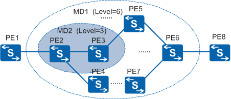
To help locate faults, MDs are separated into levels 0-7. A higher level indicates a larger area that the MD covers. An MD can be discreet from other MDs, overlap with other MDs, or be nested within another MD. Lower-level MDs can be nested within higher-level MDs, but higher-level MDs cannot be nested within lower-level MDs.
Nesting MDs improves fault diagnosis. In Figure 1, MD2 is nested within MD1. If a fault occurs in MD1, PE2 through PE7 and all the links between the PEs are checked. If no fault is detected in MD2, PE2, PE3, and PE4 are working correctly. This indicates that the fault has occurred on PE5, PE6, or PE7 or on a link between these PEs.
Nested MDs can monitor the connectivity of the higher-level MDs into which they are nested. Level settings allow 802.1ag packets to transparently travel through a nested MD. In Figure 1, MD2 is a level 3 is nested into MD1 with level 6. The 802.1ag packets must transparently pass through MD2 to monitor connectivity of MD1. The level setting allows 802.1ag packets to pass through MD2 to monitor connectivity of MD1, but also prevents 802.1ag packets that monitor MD2 connectivity from passing through MD1.
802.1ag packets are exchanged and CFM functions are implemented based on MDs. Properly planned MDs help network administrators locate faults.
Default MD
According to Std 802.1ag-2007, each device can be configured with a single default MD which has the highest priority. Figure 2 shows default MDs configured on devices within nested MDs.
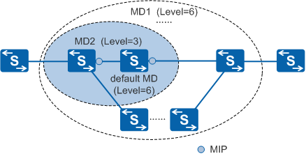
If default MDs with the same level as higher-level MDs are configured on devices in lower-level MDs, maintenance association intermediate points (MIPs) are generated based on default MDs. These MIPs send loopback reply (LBR) or linktrace reply (LTR) messages to devices in higher-level MDs. CFM detects topology changes and monitors the connectivity of both higher- and lower-level MDs.
The level of the default MD must be higher than the level of all MDs to which MEPs configured on the local device belong. The default MD must also be of the same level as the highest level MD to which the device belongs. The default MD transmits higher-level continuity check messages (CCMs) and creates MIPs to send LTR messages.
IEEE Std 802.1ag-2007 states that one default MD can be configured on each device and can be associated with multiple virtual local area networks (VLANs). VLAN interfaces can automatically generate MIPs based on the default MDs according to specified generation rules.
MA
MAs can be configured in an MD as needed. Each MA contains MEPs. MAs are identified by an MD name and an MA name.
An MA serves a specific service, such as a VLAN. A MEP in an MA sends packets carrying tags of the specific service and receives packets sent by other MEPs in the MA.
MEP
MEPs are located at the edge of an MD and MA. The service type and level of packets sent by a MEP are determined by the MD and MA to which the MEP belongs. A MEP processes packets at specific levels based on its own level, and sends packets carrying its own level. If a MEP receives a packet carrying a level higher than its own, the MEP does not process the packet and instead loops it along the reverse path. If a MEP receives a packet carrying a level lower than or equal to its own, it processes the packet.
MEPs are configured on interfaces. The MEP level is equal to the MD level.
MEPs configured on CFM-enabled devices are called local MEPs. MEPs configured on other devices in the same MA are called remote maintenance association end points (RMEPs).
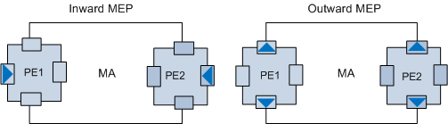
Inward-facing MEP: sends packets to other interfaces on the same device.
Outward-facing MEP: sends packets to the interface on which the MEP is configured.
MIP
MIPs are located on a link between two MEPs within an MD, facilitating management. A higher number of MIPs present on a network increases the ease of network management and control. Carriers set up more MIPs for important services than they do for ordinary services.
MIP creation modes
MIPs can be manually created on interfaces or automatically generated based on rules. Table 2 lists MIP creation modes.
Creation Mode |
Description |
|---|---|
Manual configuration |
Only IEEE Std 802.1ag-2007 supports manual MIP configuration. The MIP level must be set. If a device has both MIPs automatically created based on rules and manually created MIPs, the manually created MIPs are used. Manually configuring individual MIPs is relatively simple. However, manually configuring a large number of MIPs becomes more difficult and increases the likelihood of configuration errors. |
Automatic creation |
IEEE Std 802.1ag-2007 and IEEE 802.1ag/Draft 7 support automatic MIP creation. A device automatically generates MIPs based on preconfigured creation rules. Configuring creation rules is complex, but properly configured rules ensure correct MIP settings. |
MIP automatic creation rules
In automatic creation mode, a device automatically creates MIPs based on a specified rule. The creation rules can be configured and are classified as default, explicit, or none, as listed in Table 3.
Version |
Manual MIPs Exist on an Interface |
Creation Rule |
MEPs Are Configured on Low Level MDs |
MIPs are Created |
|---|---|---|---|---|
IEEE 802.1ag/Draft 7.0 |
N/A |
Default |
No |
Yes |
Explicit |
Yes |
Yes |
||
None |
N/A |
N/A |
||
IEEE Std 802.1ag-2007 |
Yes |
N/A |
N/A |
No |
No |
Default |
No |
Yes |
|
Explicit |
Yes |
Yes |
||
None |
N/A |
N/A |

Identify a service instance associated with the MD.
Query all interfaces in the service instance and check whether MEPs are configured on these interfaces.
Query levels of all MEPs and locate the MEP with the highest level.
MIPs are calculated separately in each service instance such as a VLAN. In a single service instance, MAs in MDs with different levels have the same VLAN ID but different levels.
Each MD on a single interface has a specific level and is associated with multiple creation rules. The creation rule with the highest priority takes effect. (Explicit rules have a higher priority than default rules.)
The level of a MIP must be higher than that of any MEP on the same interface.
Explicit rules apply only to interfaces with configured MEPs.
A single MIP can be generated on a single interface. If multiple rules for generating MIPs with different levels are used, a MIP with the lowest level is generated.
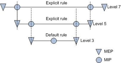
MIP creation rules help detect and locate faults by level.
For example, CCMs are sent to detect a fault in a level-7 MD on the network shown in Figure 4. Loopback or linktrace is used to locate the fault along the link between MIPs in a level-5 MD. This process is repeated until the faulty link or device is located.
The following example illustrates how to create a MIP based on a default rule defined in IEEE Std 802.1ag-2007.
In Figure 5, MD1 through MD5 are nested into MD7, and MD2 through MD5 are nested into MD1. MD7 has a higher level than MD1 through MD5, and MD1 has a higher level than MD2 through MD5. Multiple MEPs are configured on SwitchA in MD1 and the MEPs belong to MDs with different levels.
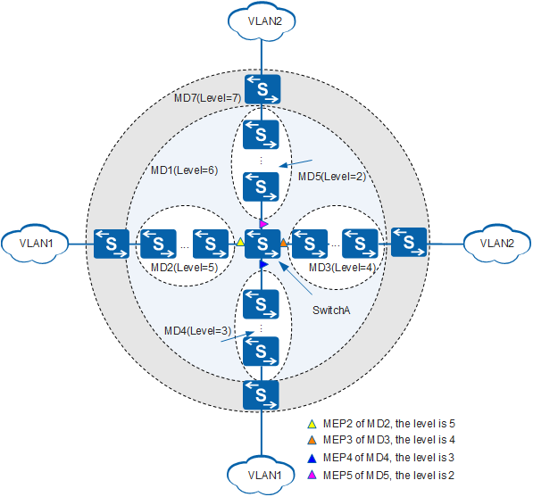
A default rule is configured on SwitchA to create a MIP in MD1. The procedure for creating the MIP is as follows:
SwitchA locates the highest-level MEP within MD1, which in this case is MEP2 at level 5. MEP levels are determined by the level of the MD to which the MEP belongs.
SwitchA compares the level of MD1 with the level of MEP2. MD1 is level 6, which is higher than MEP2's level of 5.
SwitchA generates a MIP at level 6.
If MDs at level 6 or higher do not exist, no MIP is generated.
If MIPs at level 1 already exist on SwitchA, MIPs at level 6 cannot be generated.
Hierarchical MP Maintenance
MEPs and MIPs are maintenance points (MPs). MPs are configured on interfaces and belong to specific MAs. Figure 6 shows an example of this.
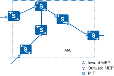
Figure 7 shows an example of a hierarchical relationship between MPs of different levels.
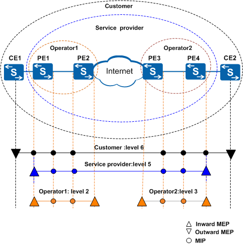
Operator 1, Operator 2, Service Provider, and Customer use MDs with levels 2, 3, 5, and 6, respectively. Higher MD levels indicate larger-scale MDs.
CFM Packets
CFM sends tagged protocol packets to detect link faults. Figure 8 shows the CFM packet format.
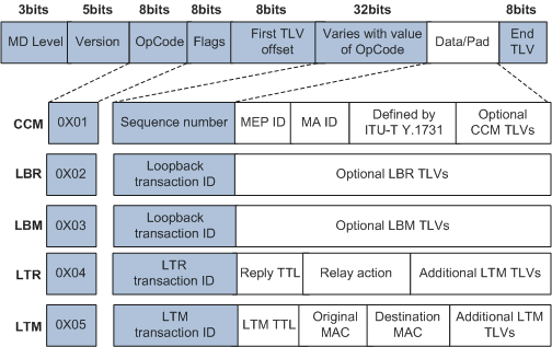
Table 4 describes the fields in CFM packets.
Field |
Description |
|---|---|
MD Level |
Level of an MD. The value ranges from 0 to 7. A larger value indicates a higher level. |
Version |
CFM version number. At the time of writing, the most recent version is 0. |
OpCode |
Message code value, specifying a specific type of CFM protocol packet. Table 5 lists types of CFM protocol packets. |
OpCode Value |
Packet Type |
Function |
|---|---|---|
0x01 |
Continuity check message (CCM) |
Monitors end-to-end link connectivity. |
0x02 |
Loopback reply (LBR) message |
Replies to a Loopback message (LBM). LBRs are sent by local nodes enabled with loopback. |
0x03 |
Loopback message (LBM) |
Is sent by an interface that initiates loopback detection. |
0x04 |
Linktrace reply (LTR) message |
Replies to a Linktrace message (LTM). LTRs are sent by local nodes enabled with linktrace. |
0x05 |
Linktrace message (LTM) |
Is sent by an interface to initiate a linktrace test. |