CFM Fundamentals
The basic functions of CFM are continuity check (CC), loopback (LB), and linktrace (LT).
Continuity Check
Continuity check (CC) monitors the continuity of links between MEPs. MEPs periodically multicast continuity check messages (CCMs) to RMEPs in the same MA. If an RMEP does not receive a CCM within a period three times the timeout interval at which CCMs are sent, the RMEP considers the path between itself and the MEP to be faulty.
CCM generation
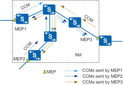
MEPs generate and send CCMs. In Figure 1, MEP1, MEP2, and MEP3 are in the same MA and send CCMs to each other at a set interval. This interval is the same for each MEP.
Each CCM is of the same level as its source MEP.
MEP database establishment
Each CFM-enabled device has a MEP database. A MEP database records information about the local MEP and RMEPs in the same MA. The local MEP and RMEPs are manually configured, and their information is automatically recorded in the MEP database.
Fault identification
If a MEP does not receive CCMs from its RMEP within a period three times the timeout interval at which CCMs are sent, the MEP considers the path between itself and the RMEP to be faulty. A log is generated to provide information for fault diagnosis. You can implement loopback or linktrace to locate the fault. MEPs in the same MA exchange CCMs to monitor links, implementing multipoint-to-multipoint (MP2MP) detection.
CCM termination
CCMs are generated and terminated by MEPs. A MEP forwards received CCMs of higher levels but drops CCMs of lower levels or the same level. CCMs from lower-level MDs are therefore not transmitted to higher-level MDs.
Loopback
Loopback is also called 802.1ag MAC ping. Similar to IP ping, loopback monitors connectivity of a path between a local MEP and an RMEP.
A MEP initiates an 802.1ag MAC ping test to monitor reachability of a MEP or MIP destination address. The source MEP and the monitored MEP or MIP must be of the same level and can be in the same MA or different MAs. The source MEP sends loopback messages (LBMs) to the MEP or MIP. After receiving these messages, the MEP or MIP replies with loopback reply messages (LBRs). Loopback helps locate faulty nodes, because faulty nodes cannot send LBRs in response to an LBM. LBMs and LBRs are unicast packets.
Figure 2 illustrates loopback implementation.
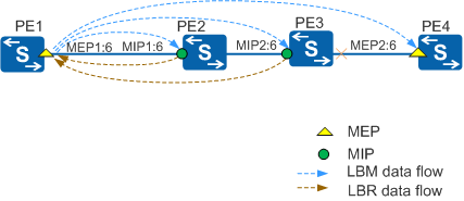
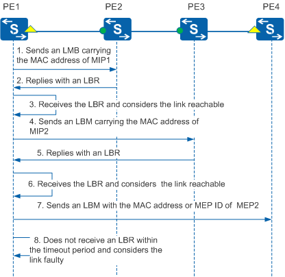
CFM is configured to monitor a path between PE1 (MEP1) and PE4 (MEP2). The MD level of both MEPs is 6. A MIP at level 6 is configured on PE2 and PE3. If a fault in a link between PE1 and PE4 is detected, loopback can be used to locate the fault. Figure 3 illustrates the loopback procedure in this example.
MEP1 can measure the network delay time based on 802.1ag MAC ping results. MEP1 can also measure frame loss ratio based on the difference between the number of LBMs and the number of LBRs.
Linktrace
Linktrace is also called 802.1ag MAC trace. Similar to IP traceroute, it identifies a path between two MEPs.
A MEP initiates an 802.1ag MAC trace test to monitor reachability of a MEP or MIP destination address. The source MEP and the monitored MEP or MIP must be of the same level and can be in the same MA or different MAs. The source MEP constructs and sends a linktrace message (LTM) to the destination MEP or MIP. After receiving the LTM, each MIP forwards the LTM and replies with a linktrace reply message (LTR). Upon receiving the LTM, the destination MEP replies with an LTR message and does not forward the LTM. Based on the LTRs received, the source MEP obtains topology information about each hop on the path. LTMs are multicast packets and LTRs are unicast packets.
Figure 4 illustrates linktrace implementation.
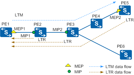
The procedure is as follows:
MEP1 sends an LTM to MEP2. The LTM carries a time to live (TTL) value and the MAC address of destination MEP2.
Once the LTM arrives at MIP1, MIP1 decrements the TTL in the LTM by 1. If the TTL is not zero, MIP1 forwards the LTM. MIP1 then replies with an LTR to MEP1. The LTR carries forwarding information and the TTL value of the LTM at the time when MIP1 received it.
After the LTM reaches MIP2 and MEP2, the process described on MIP1 is repeated for MIP2 and MEP2. In addition, MEP2 discovers that its MAC address is the destination address carried in the LTM and therefore does not forward the LTM.
The LTRs from MIP1, MIP2, and MEP2 provide MEP1 with information about the forwarding path between MEP1 and MEP2.
If a fault occurs on the path between MEP1 and MEP2, the faulty MEP or MIP cannot receive LTMs or reply with LTRs. MEP1 can locate the faulty node based on where the response failure occurs. For example, if the link between MEP1 and MIP2 works properly, but the link between MIP2 and MEP2 is faulty, MEP1 cannot receive LTRs from MEP2. However, it can still receive LTRs from MIP1 and MIP2. MEP1 then considers the path between MIP2 and MEP2 to be faulty.