Understanding Y.1731
Function Overview
Fault management functions include continuity check (CC), loopback (LB), and linktrace (LT). Y.1731 fault management is similar to CFM fault management.
Performance monitoring functions include single-ended synthetic loss measurement, one- and two-way frame delay measurement and alarm indication signal (AIS) on virtual local area networks (VLANs).

Only the S5720-EI, S5720-HI, S5720I-SI, S5720S-SI, S5720-SI, S5735-S, S5735S-S, S5735-S-I, S5730-HI, S5730S-EI, S5730-SI, S5731-H, S5731-S, S5731S-H, S5731S-S, S5732-H, S6720-EI, S6720-HI, S6720-LI, S6720S-EI, S6720S-LI, S6720S-SI, S6720-SI, S6730-H, S6730S-H, S6730-S, and S6730S-S support AIS.
Function |
Purpose |
Usage |
|---|---|---|
Collects frame loss statistics to assess the quality of links between MEPs, independent of continuity check (CC). |
To collect frame loss statistics, select either single- or dual-ended frame loss measurement:
|
|
Collects frame loss statistics to assess link quality on CFM CC-enabled devices. |
||
Measures the network delay time on a unidirectional link between MEPs. |
To measure the link delay time, select either one- or two-way frame delay measurement:
|
|
Measures the network delay time on a bidirectional link between MEPs. |
||
Collects frame loss statistics on point-to-multipoint links to monitor link quality. |
Single-ended synthetic frame LM is used to collect accurate frame loss statistics on point-to-multipoint links. |
|
Detects server-layer faults and suppresses alarms, minimizing the impact on network management systems (NMSs). |
AIS is used to suppress local alarms in the scenario where faults must be rapidly detected. When CFM detects connectivity faults, AIS suppresses generated alarms. |
|
Identifies faults and discovers RMEPs. |
|
ETH-LM
Ethernet frame loss measurement (ETH-LM) enables a local MEP and its RMEP to exchange ETH-LM frames to collect frame loss statistics on end-to-end links. ETH-LM modes are classified into near-end ETH-LM and far-end ETH-LM.
Near-end ETH-LM applies to an inbound interface, and far-end ETH-LM applies to an outbound interface on a MEP. ETH-LM counts the number of errored frame seconds to determine the duration when a link is unavailable.
Single-ended frame loss measurement
Frame loss measurement can be implemented in either of the following modes:On-demand measurement collects single-ended frame loss statistics at a time or a specific number of times for diagnosis.
Proactive measurement collects single-ended frame loss statistics periodically.
A local MEP sends a loss measurement message (LMM) carrying an ETH-LM request to its RMEP. After receiving the request, the RMEP replies with a loss measurement reply (LMR) carrying an ETH-LM response. Figure 1 illustrates the procedure for single-ended frame loss measurement.
The process of single-ended frame loss measurement is as follows:The local MEP sends an ETH-LMM (a frame containing ETH-LM request information) to the RMEP. The ETH-LMM carries a transmit counter indicating the time at which the message is sent by the local end.
After receiving the ETH-LMM, the RMEP replies with an ETH-LMR (a frame containing ETH-LM response information).
After receiving the ETH-LMR, the local MEP obtains corresponding measurement information based on message contents and calculates the frame loss rate.
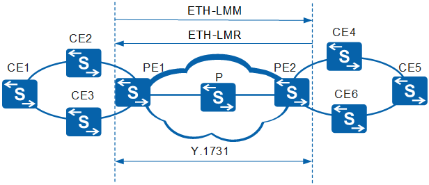
After single-ended frame loss measurement is enabled, a MEP on provider edge PE1 sends an ETH-LMM containing an ETH-LM request to an RMEP on PE2. The MEP then receives an ETH-LMR message containing an ETH-LM response from the RMEP on PE2. The ETH-LMM carries a local transmit counter TxFCl (with the value of TxFCf), indicating the time when the message is sent by the local MEP. After receiving the ETH-LMM, PE2 replies with an ETH-LMR message, containing the following information:
TxFCf: copied from the ETH-LMM
RxFCf: value of the local counter RxFCl at the time the ETH-LMM is received
TxFCb: value of the local counter TxFCl at the time the ETH-LMR is transmitted
After receiving the ETH-LMR message, PE1 measures near- and far-end frame loss based on the following values:
Received ETH-LMR message's TxFCf, RxFCf, and TxFCb values and local counter RxFCl value that is the time when this ETH-LMR message was received. These values are represented as TxFCf[tc], RxFCf[tc], TxFCb[tc], and RxFCl[tc].
tc indicates the time when this ETH-LMR message was received.
Previously received ETH-LMR message's TxFCf, RxFCf, and TxFCb values and local counter RxFCl value that is the time when this ETH-LMR message was received. These values are represented as TxFCf[tp], RxFCf[tp], TxFCb[tp], and RxFCl[tp].
tp indicates the time when the previous ETH-LMR message was received.
Far-end frame loss = |TxFCf[tc] - TxFCf[tp]| - |RxFCf[tc] - RxFCf[tp]|
Near-end frame loss = |TxFCb[tc] - TxFCb[tp]| - |RxFCl[tc] - RxFCl[tp]|
Dual-ended frame loss measurement
This method measures frame loss periodically, implementing error management. Each MEP periodically sends an ETH-LMM containing an ETH-LM request to its RMEP. After receiving the ETH-LMM, a MEP collects near- and far-end frame loss statistics and does not forward the ETH-LMM. Figure 2 illustrates the procedure for dual-ended frame loss measurement.
The process of dual-ended frame loss measurement is as follows:
Each MEP sends a frame containing ETH-LM request information to RMEPs. Here, the frame containing ETH-LM request information is called a continuity check message (CCM).
Each MEP processes the received CCMs and measures the number of frames lost on both the local and remote ends.
Each MEP obtains corresponding measurement information based on contents in the CCMs and calculates the frame loss rate.
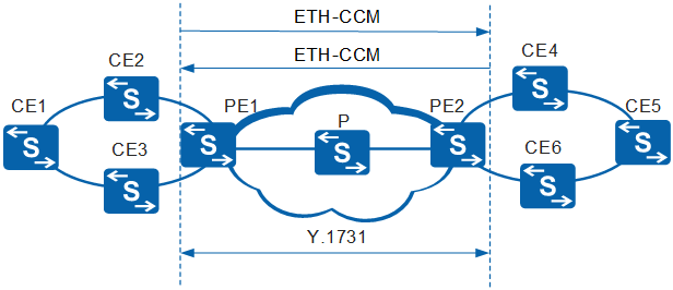
After dual-ended frame loss measurement is configured, each MEP periodically sends a CCM containing an ETH-LM request to its RMEP. After receiving the CCM, an RMEP collects near- and far-end frame loss statistics and does not forward the message. The CCM contains the following information:
TxFCf: value of the local counter TxFCl at the time the CCM are transmitted
RxFCb: value of the local counter RxFCl at the time the last CCM is received from the RMEP
TxFCb: value of TxFCf in the last received CCM
PE1 uses received information to measure near- and far-end frame loss based on the following values:
Received CCM's TxFCf, RxFCb, and TxFCb values and local counter RxFCl value that is the time when this CCM was received. These values are represented as TxFCf[tc], RxFCb[tc], TxFCb[tc], and RxFCl[tc].
tc indicates the time when the current CCM is received.
Previously received CCM's TxFCf, RxFCb, and TxFCb values and local counter RxFCl value that is the time when this CCM was received. These values are represented as TxFCf[tp], RxFCb[tp], TxFCb[tp], and RxFCl[tp].
tp indicates the time when the previous CCM was received.
Far-end frame loss = |TxFCb[tc] - TxFCb[tp]| - |RxFCb[tc] - RxFCb[tp]|
Near-end frame loss = |TxFCf[tc] - TxFCb[tp]| - |RxFCl[tc] - RxFCl[tp]|
ETH-DM
Delay measurement (DM) measures the delay time and delay variation. A MEP sends a message carrying ETH-DM information to its RMEP and then receives a response message carrying ETH-DM information from its RMEP.
One-way frame delay measurement
A MEP sends a 1DM message carrying one-way ETH-DM information to its RMEP. After receiving this message, the RMEP measures the one-way frame delay or delay variation.
One-way frame delay measurement can be implemented only after the MEP synchronizes the time with its RMEP. The delay variation can be measured regardless of whether the MEP synchronizes the time with its RMEP. If a MEP synchronizes its time with its RMEP, the one-way frame delay and delay variation can be measured. If the time is not synchronized, only the one-way delay variation can be measured.
One-way frame delay measurement can be implemented in either of the following modes:On-demand measurement calculates the one-way frame delay at a time or a specific number of times for diagnosis.
Proactive measurement calculates the one-way frame delay periodically.
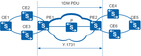
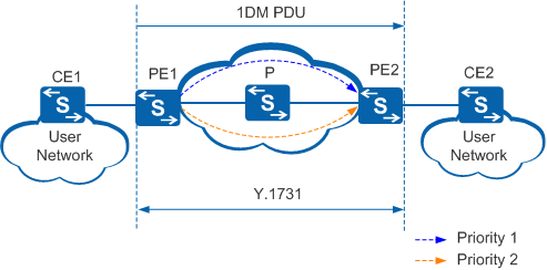
In on-demand or proactive mode, a MEP sends 1DM frames to its RMEP. Figure 3 illustrates the procedure for one-way delay measurement.
One-way frame delay measurement is implemented on an end-to-end link between a local MEP and its RMEP by exchanging 1DM frames. After one-way frame delay measurement is configured, a MEP periodically sends 1DM frames carrying TxTimeStampf (the time when the 1DM frame was sent). After receiving a 1DM frame, the RMEP parses TxTimeStampf and compares this value with RxTimef (the time when the 1DM frame was received). The RMEP calculates the one-way frame delay based on these values using the following formula:
Frame delay = RxTimef - TxTimeStampf
The frame delay value can be used to measure the delay variation.
A delay variation is an absolute difference between two delays.
Service packets are prioritized based on 802.1p priorities and are transmitted using different policies. Traffic passing through a P on the network shown in Figure 4 carries 802.1p priority values of 1 and 2.
One-way delay measurement is enabled on PE1 to send traffic with the priority value of 1 to measure the frame delay on a link between PE1 and PE2. Traffic with the priority value of 2 is also sent. After receiving traffic with the priority values of 1 and 2, the P forwards traffic with a higher priority, delaying the arrival of traffic with the priority value of 1 at PE2. As a result, the frame delay calculated on PE2 is inaccurate.
802.1p priority-based one-way frame delay measurement can be enabled to obtain accurate results.
Two-way frame delay measurement
A MEP sends a delay measurement message (DMM) carrying an ETH-DM request to its RMEP. After receiving the DMM, the RMEP sends a delay measurement reply (DMR) carrying an ETH-DM response to the MEP.
Two-way frame delay measurement can be implemented in either of the following modes:The on-demand measurement calculates the two-way frame delay at a time for diagnosis.
The proactive measurement calculates the two-way frame delay periodically.
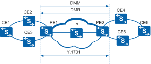
Figure 5 illustrates the procedure for two-way delay measurement.
Two-way frame delay measurement is performed by a local MEP to send a DMM to its RMEP and then receive a DMR from the RMEP. After the two-way frame delay measurement is configured, a MEP periodically sends DMMs carrying TxTimeStampf (the time when the DMM was sent). After receiving the DMM, the RMEP replies with a DMR. The DMR carries RxTimeStampf (the time when the DMM was received) and TxTimeStampb (the time when the DMR was sent). The value in every field of the DMM is copied to the DMR except that the source and destination MAC addresses were interchanged. Upon receiving the DMR, the MEP calculates the two-way frame delay by using the following formula:
Frame delay = (RxTimeb - TxTimeStampf) - (TxTimeStampb - RxTimeStampf)
The frame delay value can be used to measure the delay variation.
A delay variation is an absolute difference between two delays.
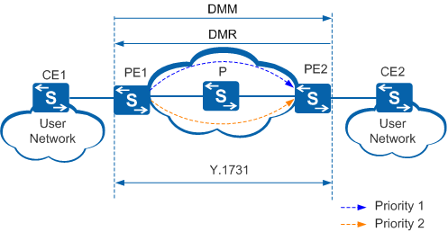
Service packets are prioritized based on 802.1p priorities and are transmitted using different policies. Traffic passing through a P on the network shown in Figure 6 carries 802.1p priority values of 1 and 2.
Two-way delay measurement is enabled on PE1 to send traffic with the priority value of 1 to measure the frame delay on a link between PE1 and PE2. Traffic with the priority value of 2 is also sent. After receiving traffic with the priority values of 1 and 2, the P forwards traffic with a higher priority, delaying the arrival of traffic with the priority value of 1 at PE2. As a result, the frame delay calculated on PE2 is inaccurate.
802.1p priority-based two-way frame delay measurement can be enabled to obtain accurate results.
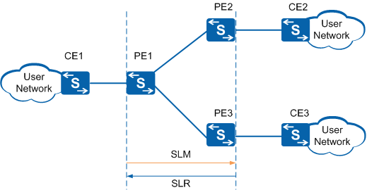
Single-ended synthetic loss measurement (SLM)
SLM measures frame loss using synthetic frames instead of data traffic. When implementing SLM, the local MEP exchanges frames containing ETH-SLM information with one or more RMEPs.
The local MEP sends frames with the ETH-SLM request information to the RMEPs.
The RMEPs send frames with the ETH-SLM reply information to the local MEP.
AIS
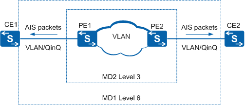
Alarm indication signal (AIS) is used to transmit fault information.
If CFM detects a fault in the link between AIS-enabled PEs, CFM sends AIS packet data units (PDUs) to CEs. After receiving the AIS PDUs, the CEs suppress alarms, minimizing the impact of a lot of alarms on a network management system (NMS).
After the link between the PEs recovers, the PEs stop sending AIS PDUs. CEs do not receive AIS PDUs during a period of time 3.5 times as long as the interval at which AIS PDUs are sent. Therefore, the CEs cancel the alarm suppression function.
Multicast MAC Ping
Fault verification
Fault verification provided by multicast MAC ping is similar to that provided by 802.1ag MAC ping. They are both used to check the reachability between the local and destination devices by sending test packets. Unlike 802.1ag MAC ping, multicast MAC ping can detect faults in links between multiple MEPs at a time.
Multicast MAC ping is applied to the networking where multiple MEPs are deployed. Multicast MAC ping is initiated by the local MEP and responded to by the RMEP.
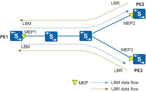
As shown in Figure 9, MEP1 on PE1 has two RMEPs, namely, MEP2 and MEP3. MEP1 initiates a multicast MAC ping probe. The probe process is as follows:In the case where the link between MEP1 and MEP2 or between MEP1 and MEP3 is normal:
MEP1 of the local device sends a multicast LBM.
After receiving the multicast LBM, MEP2 and MEP3 reply with an LBR.
The local device receives the LBRs and displays the contents of the LBRs.
- In the case where the link between MEP1 and MEP2 or between MEP1 and MEP3 is faulty:
MEP1 of the local device sends a multicast LBM.
MEP1 does not receive any LBR from the RMEPs within a specified timeout period. The output of the related command shows that a fault occurs on the link between MEP1 and MEP2 or the link between MEP1 and MEP3.
RMEP discovery
As shown in Figure 9, RMEPs need to be configured for MEP1 of PE1. The IDs and MAC addresses of the RMEPs may be unknown. Therefore, multicast MAC ping can be performed to discover the RMEPs of MEP1. The process of multicast MAC ping is as follows:MEP1 of the local device sends a multicast LBM.
After receiving the multicast LBM, MEP2 and MEP3 reply with an LBR.
The local device receives the LBRs and displays the contents of the LBRs. The LBRs contain the MAC addresses of the RMEPs, MEP IDs, and delay.