Load Balancing Modes of Link Aggregation
Context
Because an Eth-Trunk between two devices consists of multiple physical links bundled together, an Eth-Trunk may transmit data frames of the same data flow over different physical links. A potential problem arises in that the second data frame may arrive at the remote device earlier than the first data frame, resulting in out-of-order packets.
To prevent out-of-order packets, Eth-Trunk uses flow-based load balancing. This mechanism uses the hash algorithm to calculate the address in a data frame and generate a hash key based on which the system searches for the outbound interface in the Eth-Trunk forwarding table. Each MAC or IP address corresponds to a hash key, so the system uses different outbound interfaces to forward data. This mechanism ensures that frames of the same data flow are forwarded on the same physical link and implements load balancing of data flows. Flow-based load balancing ensures that data is transmitted in the correct sequence, but cannot ensure efficient bandwidth usage.
Traffic Forwarding
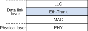
In Figure 1, an Eth-Trunk is located at the data link layer, between the MAC address and LLC sub-layers.
The Eth-Trunk module maintains a forwarding table that consists of the following fields:
Hash key
The hash key is calculated through the hash algorithm based on the MAC address or IP address in a data frame.
Interface number
Eth-Trunk forwarding entries are limited by the maximum number of member interfaces in an Eth-Trunk. Different hash keys map to different outbound interfaces.
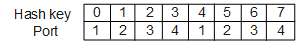
For example, an Eth-Trunk supports a maximum of eight member interfaces. If physical interfaces 1, 2, 3, and 4 are bundled into an Eth-Trunk, the Eth-Trunk forwarding table contains eight entries, as shown in Figure 2. In the Eth-Trunk forwarding table, hash keys are 0, 1, 2, 3, 4, 5, 6, and 7, and the corresponding interface numbers are 1, 2, 3, 4, 1, 2, 3, and 4.
The Eth-Trunk module uses the Eth-Trunk forwarding table to forward data frames according to the following process:
The Eth-Trunk module receives a packet from the MAC sub-layer, and then extracts its source MAC address/IP address or destination MAC address/IP address.
The Eth-Trunk module calculates the hash key using the hash algorithm.
Based on the hash key, the Eth-Trunk module searches for the interface number in the Eth-Trunk forwarding table, and then sends the data frame from the corresponding interface.
Load Balancing Modes
You can set the load balancing mode based on traffic models. When a parameter of traffic changes frequently, you can set the load balancing mode based on this parameter to ensure that the traffic is load balanced evenly. For example, if IP addresses in packets change frequently, use the load balancing mode based on the destination IP address, source IP address, or source and destination IP addresses. If MAC addresses in packets change frequently and IP addresses are fixed, use the load balancing mode based on the destination MAC address, source MAC address, or source and destination MAC addresses.
According to your network requirements, you can carry out load balancing based on the following information:
- Source MAC addresses of data frames
- Destination MAC address of data frames
- Exclusive-Or result of source and destination MAC addresses of data frames
- Source IP addresses of data frames
- Destination IP addresses of data frames
- Exclusive-Or result of source and destination IP addresses of data frames
- VLAN IDs and source physical interface numbers for Layer 2, IPv4, IPv6, and MPLS packets in enhanced load balancing mode
For example, DeviceA has two TCP packet flows. For one TCP packet flow, the source IP address is 192.168.1.1 (MAC address: a-a-a; source port number: 50), and the destination IP address is 172.16.1.1 (MAC address: b-b-b; destination port number: 2000). For the other TCP packet flow, the source IP address is 192.168.1.1 (MAC address: a-a-a; source port number: 60), and the destination IP address is 10.1.1.1 (MAC address: c-c-c; destination port number: 2000). If load balancing based on the source MAC address is configured on DeviceA, only one outbound interface is available for sending packets out. On the other hand, if load balancing based on the destination IP address is configured on DeviceA, packets destined for different destination IP addresses are sent out through different outbound interfaces.
When configuring a load balancing mode, pay attention to the following points:
- The load balancing mode only takes effect on traffic leaving the outbound interface. If traffic entering the inbound interface is uneven, change the load balancing mode of the uplink outbound interface.
- When possible, ensure data flows are load balanced among all active links. If data flows are transmitted over one link, traffic congestion may occur, affecting services.
For example, when data frames have only one destination MAC address and IP address, use load balancing based on the source MAC address and IP address of data frames. If load balancing based on the destination MAC address and IP address is used, traffic is transmitted over one link, causing congestion.