E-Trunk
Enhanced Trunk (E-Trunk) is an extension of the Link Aggregation Control Protocol (LACP). E-Trunk controls and implements link aggregation among multiple devices, whereas LACP does so for just one device. While LACP can guarantee reliability when a card fails, E-Trunk does so even when a device fails.
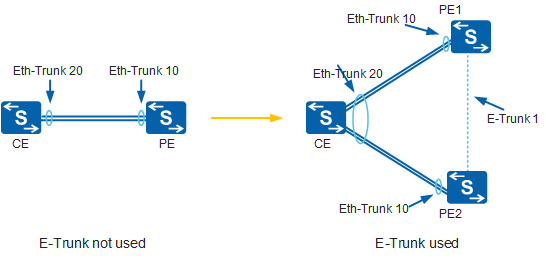
E-Trunk is suitable to scenarios where a CE is dual-homed to a network. In this scenario, E-Trunk can be used to protect PEs and links between the CE and PEs. In Figure 1, without E-Trunk, a CE can be connected through an Eth-Trunk link to only one PE. If the Eth-Trunk or PE fails, the CE cannot communicate with the PE. By using E-Trunk, the CE can be dual-homed to PEs, providing device-level protection.

E-Trunk is supported by only the following models: S5720-EI, S5720-HI, S5720I-SI, S5720S-SI, S5720-SI, S5735-S, S5735S-S, S5735-S-I, S5730-HI, S5730S-EI, S5730-SI, S5731-H, S5731-S, S5731S-H, S5731S-S, S5732-H, S6720-EI, S6720-HI, S6720-LI, S6720S-EI, S6720S-LI, S6720S-SI, S6720-SI, S6730-H, S6730S-H, S6730-S, and S6730S-S.
Basic Concepts
Table 1 describes the basic concepts of E-Trunk.
Concept |
Description |
|---|---|
LACP system priority |
The LACP system priority is used to differentiate priorities of devices at both ends of an Eth-Trunk link. A smaller value indicates a higher LACP system priority. |
System ID |
The system ID is used to determine priorities of the two devices at both ends of an Eth-Trunk link if their LACP priorities are the same. The smaller the system ID, the higher the priority. By default, the system ID is the MAC address of an Eth-Trunk. |
E-Trunk priority |
The E-Trunk priorities determine the master/backup status of two devices in a LAG. A smaller E-Trunk priority value indicates a higher E-Trunk priority. |
E-Trunk ID |
An E-Trunk ID is an integer that uniquely identifies an E-Trunk. |
Eth-Trunk working mode |
The Eth-Trunk can work in one of the following modes:
|
Timeout interval |
When working normally, the master and backup devices in an E-Trunk periodically send hello packets to each other. If the backup device does not receive any hello packets within the timeout interval, it becomes the master device. |
E-Trunk Working Mechanism
In Figure 2, the CE is directly connected to PE1 and PE2, and the E-Trunk runs between PE1 and PE2.
The same Eth-Trunk and E-Trunk are created on PE1 and PE2, and the Eth-Trunks are added to the E-Trunk.
An Eth-Trunk in LACP mode is configured on the CE, and the CE is connected to PE1 and PE2 through the Eth-Trunk. The E-Trunk is invisible to the CE.
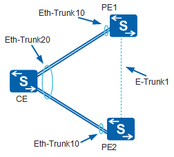
Figure 2 is used as an example to describe how E-Trunk is implemented.
Master/Backup status negotiation
Determine the E-Trunk master/backup status.
PE1 and PE2 negotiate the E-Trunk master/backup status by exchanging E-Trunk packets. After the negotiation, one PE functions as the master and the other as the backup.
The master/backup status of a PE depends on the E-Trunk priority and E-Trunk ID carried in E-Trunk packets. The PE with a higher E-Trunk priority functions as the master device. If PEs have the same E-Trunk priority, the PE with a smaller E-Trunk system ID functions as the master device.
Determine the master/backup status of a member Eth-Trunk in the E-Trunk.
The master/backup status of a member Eth-Trunk in the E-Trunk depends on its E-Trunk status and the remote Eth-Trunk status.
In Figure 2, PE1 and PE2 are at opposite ends of the E-Trunk link. In this example, PE1 is considered the local device and PE2 is the remote device.
Table 2 describes the status of each member Eth-Trunk in the E-Trunk.
Table 2 Master/Backup status of an E-Trunk and its member Eth-Trunks Local E-Trunk Status
Working Mode of the Local Eth-Trunk
Remote Eth-Trunk Status
Local Eth-Trunk Status
-
Forcible master
-
Master
-
Forcible backup
-
Backup
Master
Automatic
Down
Master
Backup
Automatic
Down
Master
Backup
Automatic
Up
Backup
In normal situations, when PE1 functions as the master device, Eth-Trunk 10 of PE1 enters the master state and its link status is Up. When PE2 functions as the backup device, Eth-Trunk 10 of PE2 enters the backup state and its link status is Down.
If the link between the CE and PE1 fails, PE1 sends an E-Trunk packet containing information about faulty Eth-Trunk 10 of PE1 to PE2. After receiving the E-Trunk packet, PE2 learns that Eth-Trunk 10 on PE1 is faulty. Eth-Trunk 10 on PE2 becomes the master. Through LACP negotiation, Eth-Trunk 10 on PE2 becomes Up. The Eth-Trunk status on PE2 becomes Up, and traffic from the CE is forwarded through PE2, preventing traffic interruption.
Sending and receiving of E-Trunk packets
E-Trunk packets carrying the source IP address and port number configured on the local device are carried over UDP. E-Trunk packets are sent in the following situations:The packet sending timer expires.
The configurations change. For example, the E-Trunk priority, packet sending interval, timeout interval multiplier, or the source/destination IP address of the E-Trunk changes, or member Eth-Trunks are added or deleted.
A member Eth-Trunk fails or recovers.
The timeout interval needs to be carried in E-Trunk packets sent from the local end so that the remote device can use the same timeout interval.
Switchback mechanism
If the Eth-Trunk on the local device in master state goes Down or the local device fails, the remote device becomes the master device and the member Eth-Trunk becomes Up.
When the local device recovers, the local Eth-Trunk enters the LACP negotiation state. After LACP informs the local E-Trunk module of the negotiation capability Up event, the local device starts the switchback delay timer. When the switchback delay timer expires, the local Eth-Trunk enters the master state and goes Up after LACP negotiation.
E-Trunk Constraints
Using Figure 2 as an example, to improve reliability of links between the CE and PEs and guarantee that traffic is properly switched between these links, pay attention to the following points:
The configurations at both ends of the E-Trunk link must be consistent. The Eth-Trunks linked directly to the PEs and the CE must be configured with the same working rate and duplex mode so that both Eth-Trunks have the same hash key and join the same E-Trunk. After the Eth-Trunks are added to the E-Trunk, both PEs must contain the same LACP system priorities and IDs. The interfaces connecting the CE to PE1 and PE2 must be added to the same Eth-Trunk. The Eth-Trunk on the CE can have a different ID from that of the PEs. For example, the CE is configured with Eth-Trunk 1, and both PEs are configured with Eth-Trunk 10.
To ensure Layer 3 connectivity, the IP address of the local PE must be the same as the local address of the remote PE and vice versa. Therefore, it is recommended that the addresses of the PEs are configured as loopback interface addresses.
The two PEs must be configured with the same security key, if necessary.