IGMP Snooping
Fundamentals
IGMP snooping is a basic Layer 2 multicast function that controls multicast traffic forwarding at the data link layer. IGMP snooping runs on a Layer 2 multicast device and analyzes IGMP messages exchanged between a Layer 3 device and hosts to set up and maintain a Layer 2 multicast forwarding table. The Layer 2 multicast device forwards multicast packets based on the Layer 2 multicast forwarding table.
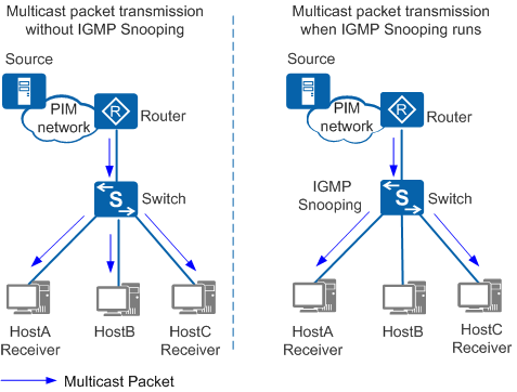
In Figure 1, the switch at the edge of the access layer forwards the multicast packets sent from the router (Layer 3 device) to receiver hosts. If the switch does not run IGMP snooping, it broadcasts multicast packets at Layer 2. After IGMP snooping is configured, the switch forwards multicast packets only to specified hosts.
With IGMP snooping configured, the switch listens to IGMP messages exchanged between the router and hosts. It analyzes packet information (such as packet type, group address, and receiving interface) to set up and maintain a Layer 2 multicast forwarding table, based on which it forwards multicast packets.
Concepts
In Figure 2, the router (Layer 3 device) receives multicast data from the multicast source and forwards the data to downstream devices. IGMP snooping is configured on SwitchA and SwitchB. Hosts A, B, and C are receiver hosts.
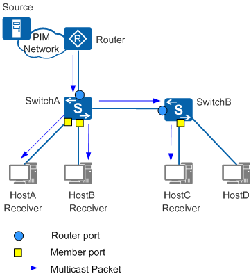
The following table describes the port roles shown in Figure 2.
Port Role |
Function |
Generation |
|---|---|---|
Router port Ports marked as blue circles on SwitchA and SwitchB NOTE:
A router port is a port of a Layer 2 multicast device connected to an upstream multicast router. "Router port" does not refer to a port on a router in this document. |
A router port receives multicast packets from a Layer 3 multicast device such as a designated router (DR) or IGMP querier. |
|
Member port Ports marked as yellow squares on SwitchA and SwitchB |
A member port is a user-side port connected to group members. A Layer 2 multicast device sends multicast data to receiver hosts through member ports. |
|
Router ports and member ports are outbound interfaces in Layer 2 multicast forwarding entries. A router port is an upstream interface, while a member port is a downstream interface. Port information learned through protocol packets is saved as dynamic entries. Manually configured port information is saved as static entries.
- Multicast group addresses can be multicast IP addresses or multicast MAC addresses mapped from multicast IP addresses. In MAC address-based forwarding mode, multicast data may be forwarded to hosts that do not require the data because multiple IP addresses are mapped to the same MAC address. The IP address-based forwarding mode can prevent this problem.
- A VLAN ID specifies a Layer 2 broadcast domain. After multicast VLAN is configured, the inbound VLAN ID is the multicast VLAN ID, and the outbound VLAN ID is a user VLAN ID. If multicast VLAN is not configured, both the inbound and outbound VLAN IDs are the ID of the VLAN to which a host belongs. For details about multicast VLAN, see Understanding Multicast VLAN Replication.
Implementation
A Layer 2 multicast device running IGMP snooping processes received IGMP protocol packets in different ways to set up Layer 2 multicast forwarding entries.
IGMP Working Phase |
IGMP Message Received on a Layer 2 Device |
Processing Method |
|---|---|---|
General query The IGMP querier periodically sends General Query messages (with destination address 224.0.0.1) to all hosts and routers on the local network segment, to check which multicast groups have members on the network segment. |
IGMP General Query message |
A Layer 2 multicast device forwards IGMP General Query messages
to all ports except the port receiving the messages in a VLAN. The
Layer 2 multicast device processes the receiving port as follows:
NOTE:
By default, the Layer 2 multicast device sets the aging time to 180 seconds when the router port receives an IGMP General Query message. The aging time is configurable. |
Membership report Membership Report messages are used
in two scenarios:
|
IGMP Report message |
A Layer 2 multicast device forwards an IGMP Report message
to all router ports in a VLAN. The device obtains the multicast group
address from the Report message and performs the following operations
on the port receiving the message:
NOTE:
After a group member port receives an IGMP Report message, its aging time is calculated using the following formula: Aging time = Robustness variable x General query interval + Maximum response time for General Query messages |
Leave of multicast members There are two phases:
|
IGMP Leave message |
The Layer 2 multicast device determines whether the multicast
group matches a forwarding entry and whether the port that receives
the message is in the outbound interface list.
The following assumes that the port receiving an IGMP
Leave message is a dynamic member port. Before the aging time of the
member port expires:
NOTE:
After a group member port receives an IGMP Leave message, its aging time is calculated using the following formula: Aging time = Robustness variable x Group-Specific query interval |
IGMP Group-Specific/Group-Source-Specific Query message |
An IGMP Group-Specific/Group-Source-Specific Query message is forwarded to the ports connected to members of specific groups. |
- If the port is included in the router port list, the Layer 2 multicast device resets the aging timer of the router port.
- If the port is not in the router port list, the Layer 2 multicast device adds it to the list and starts the aging timer.

When the Layer 2 multicast device receives a PIM Hello message, it sets the aging time of the router port to the Holdtime value in the Hello message.
If a static router port is configured, the Layer 2 multicast device forwards received IGMP Report and Leave messages to the static router port. If a static member port is configured for a multicast group, the Layer 2 multicast device adds the port to the outbound interface list for the multicast group.
After a Layer 2 multicast forwarding table is set up, the Layer 2 multicast device searches the multicast forwarding table for outbound interfaces of multicast data packets according to the VLAN IDs and destination addresses (group addresses) of the packets. If outbound interfaces are found for a packet, the Layer 2 multicast device forwards the packet to the matching member ports and router ports. If no outbound interface is found, the Layer 2 multicast device drops the packet or broadcasts the packet in the VLAN.
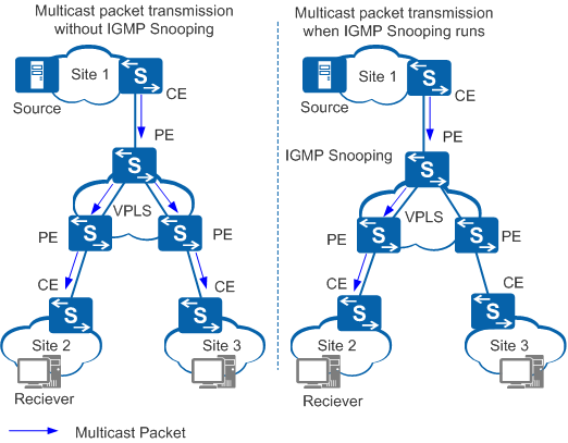
IGMP Snooping on a VPLS Network
On a virtual private LAN service (VPLS) network, when an upstream device needs to send multicast packets to users in a virtual switch instance (VSI), the provider edge (PE) devices on the VPLS network forward the multicast packets to customer edge (CE) devices. The CE devices then forward the multicast packets to users in the VSI so that users can watch the programs they order. As shown in Figure 3, if IGMP snooping is not configured on the VPLS network, multicast data packets are forwarded to all the PE devices bound to the VSI. This wastes network bandwidth.
After IGMP snooping is configured on PE devices, multicast data packets are sent only to the PE devices connected to the sites that require the multicast data.
For details about VPLS fundamentals and configuration, see VPLS Configuration in the S2720, S5700, and S6700 V200R019C10 Configuration Guide - VPN.