Network-Level Packet Loss Measurement Model
Network-level packet loss measurement is based on IP Flow Performance Measurement (IP FPM). IP FPM can measure network performance indicators, such as packet loss ratio and number of lost packets, on point-to-point networks or multipoint-to-multipoint networks. The measurement model consists of Target Flow, Transit Network, and Measurement System.
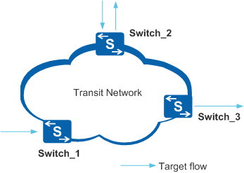
Target Flow
Service packets on a network are the targets of IP FPM measurement. These service packets form target flows. Through network-level packet loss measurement, iPCA measures lost packets in the target flows passing through a network.
A target flow must be specified before measurement starts. As listed in Table 1, a target flow is uniquely identified by fields in the IP packet. You can specify one field or a combination of multiple fields to determine a target flow. If you specify several fields, the range of target flow is large. To make the statistics more accurate, specify a greater number of fields.
Field |
Description |
|---|---|
Source IP address |
Source IP address (or source IP address field) of a target flow, located in the IP packet header |
Destination IP address |
Destination IP address (or destination IP address field) of a target flow, located in the IP packet header |
Protocol type |
Protocol carried by a target flow, for example, ICMP, TCP, and UDP, located in the IP packet header |
Source port number |
Layer 4 source port number of a target flow, located in the TCP or UDP packet header |
Destination port number |
Layer 4 destination port number of a target flow, located in the TCP or UDP packet header |
DSCP |
DSCP value in a target flow, located in the IP packet header |
Transit Network
A transit network does not generate or terminate target flows. A transit network is a Layer 2 or Layer 3 network (IP or MPLS network), or a Layer 2 and Layer 3 mixed network. iPCA requires that every node on the transit network have reachable routes to each other.
Measurement System
The measurement system is a logical concept. It is responsible for counting the received and sent packets on the ingress and egress of a network, and providing network performance indicators. The system consists of three roles: Target Logical Port (TLP), Data Collecting Point (DCP), and Measurement Control Point (MCP), as shown in Figure 2.
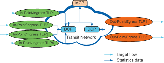
TLP
TLPs are the observation points distributed along the network edge. They are the interfaces on network devices. For a target flow, the upstream TLP (also called in-point TLP or ingress TLP) receives packets and colors the specified bits in packets; the downstream TLP (also called out-point TLP or egress TLP) removes the color flags from the specified bits and sends packets out.
TLPs execute measurement activities and generate statistics (such as number of sent and received packets and time stamps).
DCP
DCPs are the statistics aggregation points. They are network devices, for example, switches. A DCP manages and controls TLPs, aggregates the statistics collected by TLPs, and sends the data to the MCP.
MCP
The MCP is the controller in the measurement system. It is also a network device, for example, a high-performance switch or an independent device in the network management center. The MCP receives statistics sent from DCPs, summarizes and calculates statistics, and reports calculation results to user terminals or the NMS. A network device can function as both an MCP and a DCP.
An enterprise network needs to transmit different types of service flows, such as voice flows and video flows. Generally, these flows pass through the same devices. When the measurement system counts the lost packets for different service flows, the statistics on different target flows must be differentiated from each other. Measurement instances are used to differentiate target flows. You can consider each measurement instance as a measurement system. The DCP and MCP collect statistics on the same target flow through the same measurement instance.
Measurement Process
In Figure 3, the network has target flow A and target flow B. The lost packets in target A and target B need to be measured when the flows pass through the transit network.
The measurement process is as follows:
- TLPA1, TLPA2, and TLPB1 color target flow A and target flow B, and generate statistics. DCP1 and DCP2 collect statistics from TLPs.
- TLPA3 and TLPB3 decolor the target flows, and generate statistics. DCP3 collects statistics from TLPs.
- DCP2 and DCP3 send statistics to the MCP through iPCA packets.
- The MCP collects statistics from DCP1, DCP2, and DCP3 and calculates the number of lost packets in target flow A and target flow B when they pass through the transit network.