Working Mechanism of Network-Level Packet Loss Measurement
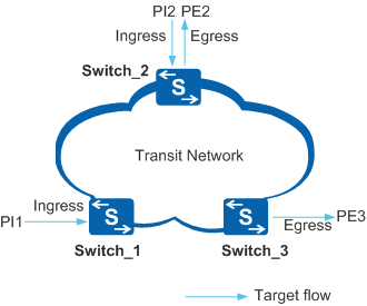
Packet loss statistics include the number of lost packets and packet loss ratio of the traffic passing through a network within a time range, which are calculated by comparing the number of packets entering a network with the number of packets leaving the network. In Figure 1, the number of packets entering the network through the ingress interface is PI(n) and the number of packets leaving the network through the egress interface is PE(n). The number of lost packets on the network is the difference between PI = PI(1) + PI(2) and PE = PE(2) + PE(3).
When using iPCA to measure packet loss, you can specify the measurement time range. iPCA then measures packet loss based on packet characteristics bits within the measurement time range. To be specific, iPCA periodically sets and resets a certain color bit in service packet headers on the ingress interface to divide a measurement time range into measurement intervals, and measures packet loss within each measurement interval.

If the measurement time range is infinite, packet loss measurement will be performed continuously until you disable it. The measurement time range can be set to 5, 10, 15, or 30 minutes. The default measurement time range is 10 minutes.
The measurement interval can be set to 1, 10, 60, or 600 seconds. The default measurement interval is 10 seconds.
Figure 1 shows an example of packet loss measurement based on packet characteristics bits. Target flows enter the network through Switch_1 and Switch_2, and leave the network through Switch_2 and Switch_3. Figure 2 illustrates how packet loss measurement is implemented based on the packet characteristics bits on each device. tn is an absolute point, and tn-tn+4 (n is smaller than or equivalent to 4) indicates a measurement interval.
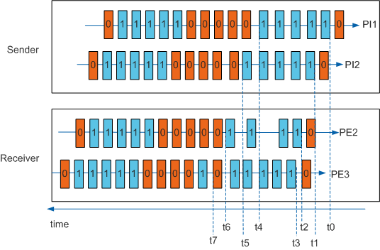
- t0: Switch_1 sets the color bits in the service packets entering the network to 1, and starts the counter to count the service packets with color bit 1 sent within the first interval.
- t1: Switch_2 sets the color bits in the service packets entering the network to 1, and starts the counter to count the packets with color bit 1 sent within the first interval.
- t2: The egress interface of Switch_2 receives the first service packet with color bit 1 in the first interval, and starts the counter to count these packets.
- t2: The egress interface of Switch_3 receives the first service packet with color bit 1 in the first interval, and starts the counter to count these packets.
- t4: Switch_1 finishes counting the service packets with color bit 1 in the first interval, and determines the number PI(1) of packets sent within the first interval.
- t5: Switch_2 finishes counting the service packets with color bit 1 in the first interval, and determines the number PI(2) of packets sent within the first interval.
- t6: Switch_2 finishes counting the service packets with color bit 1 in the first interval, and determines the number PE(2) of packets received within the first interval. The egress interface of Switch_2 removes the color flags from service packets.
t7: Switch_3 finishes counting the service packets with color bit 1 in the first interval, and determines the number PE(3) of packets received within the first interval. The egress interface of Switch_2 removes the color flags from service packets.
If Switch_3 receives a packet with color bit 0 during this measurement interval for reasons such as out-of-order packet delivery, this packet is not counted within the interval.
The number (LostPacket) of lost packets within this measurement interval is PI(1) + PI(2) - PE(2) - PE(3), and the packet loss ratio (LostPacketRate) is LostPacket/[PI(1) + PI(2)].
To ensure statistics accuracy, the sender and receiver must follow the same standard to mark the measurement time so that they can obtain the data in the same period of time. Therefore, time synchronization between the two devices is a prerequisite of packet loss measurement at the network level. Before configuring iPCA, configure NTP to allow the switches to synchronize time with each other.
Most switches support the NTP protocol. An iPCA measurement interval is usually several seconds. The precision of NTP, 50 ms, can ensure the accuracy of iPCA measurement. For details about NTP, see NTP Configuration in the S2720, S5700, and S6700 V200R019C10 Configuration Guide - Device Management.