Understanding Layer 2 Protocol Tunneling
- The destination multicast MAC address of a Layer 2 protocol packet is replaced with a specified multicast MAC address on the ingress Provider Edge (PE) of the ISP network.
- The devices on the ISP network determine whether to process the protocol packet based on the configured transparent transmission mode.
- When the Layer 2 protocol packet reaches the egress, the PE restores the destination multicast MAC address of the Layer 2 protocol packet to the standard destination multicast MAC address based on the mapping between the specified destination multicast MAC address and the Layer 2 protocol configured on the device. The egress PE also determines whether to process the packet based on the configured transparent transmission mode.
To transparently transmit Layer 2 protocol packets on the ISP network, ensure that the following requirements are met:
All branches of a user network can receive Layer 2 protocol packets from other branches.
Layer 2 protocol packets of a user network cannot be processed by the CPU of devices on the ISP network.
Layer 2 protocol packets from different user networks must be isolated and not affect each other.
Huawei switches support the following Layer 2 protocol tunneling modes in different scenarios:
Interface-based
VLAN-based
QinQ-based
VPLS-based
Interface-based Layer 2 Protocol Tunneling

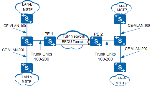
In Figure 1, each PE interface connects to one user network. These user networks do not belong to the same LAN. If BPDUs received from user networks do not carry any VLAN tag, the PE must identify the LAN that the BPDUs come from. BPDUs of a user network on LAN-A must be sent to other user networks on LAN-A. In addition, BPDUs must not be processed by devices on the ISP network.
Change the default multicast MAC address of the Layer 2 protocol packet that can be identified by the devices on the ISP network to another multicast MAC address. This method only applies to STP, RSTP, or MSTP, and the configuration command is bpdu-tunnel stp bridge role provider.
Set roles of all ISP network devices to provider so that the multicast MAC addresses of BPDUs sent by these devices are changed to 01-80-C2-00-00-08.
Set roles of all user network devices to customer so that the multicast MAC addresses of BPDUs sent by the user network are 01-80-C2-00-00-00.
Add interfaces that connect to the same user network to the same VLAN on ISP network devices. PEs add VLAN tags to received Layer 2 protocol packets based on default VLAN IDs of interfaces.
PEs (providers) do not consider the packets as Layer 2 BPDUs and do not send them to the CPU. Instead, PEs select a Layer 2 tunnel to forward the packets based on the default VLAN IDs of the interfaces.
Internal nodes on the ISP network forward the packets through the ISP network as common Layer 2 packets.
PEs on the ISP network forward the packets to CEs without modifying the packets.
Replace the original multicast MAC address of the Layer 2 protocol packet with a specified multicast MAC address.
Add the interfaces that connect to the same user network to the same VLAN on the switch of the ISP network. After receiving and identifying the Layer 2 protocol packet (such as a BPDU of the STP protocol) from the user network, the switch on the ISP network adds the default VLAN ID of the interface to the Layer 2 protocol packet. This method applies to all modes of Layer 2 protocol tunneling.
The ingress PE on the ISP network replaces the standard destination multicast MAC address of the Layer 2 protocol packet with the specified destination multicast MAC address based on the mapping between the specified destination multicast MAC address and the Layer 2 protocol.
Internal nodes on the ISP network forward the packet as a common Layer 2 packet through the ISP network.
The egress PE on the ISP network restores the original standard destination MAC address of the packet based on the mapping between the specified destination multicast MAC address and the Layer 2 protocol and forwards the packet to the CE.
VLAN-based Layer 2 Protocol Tunneling
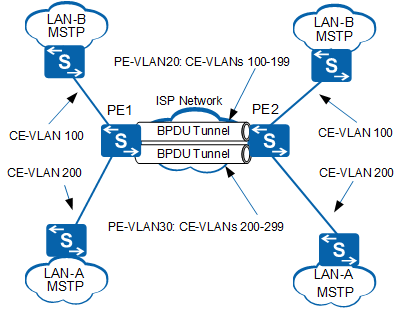
In most cases, a PE serves as an aggregation device. In Figure 2, the aggregation interface on PE1 receives Layer 2 protocol packets from LAN-A and LAN-B. To differentiate BPDUs from two LANs, BPDUs sent from CEs to PEs must have VLAN tags. Packets sent from LAN-A contain VLAN ID 200 and packets sent from LAN-B contain VLAN ID 100. BPDUs of a user network in LAN-A must be forwarded to other user networks in LAN-A, but not to user networks in LAN-B. In addition, BPDUs cannot be processed by PEs on the ISP network. In this case, you can configure VLAN-based Layer 2 protocol tunneling on PEs, so that Layer 2 protocol packets can traverse the ISP network through Layer 2 tunnels.
Change the default multicast MAC address of the Layer 2 protocol packet that can be identified by the devices on the ISP network to another multicast MAC address. This method only applies to STP, RSTP, or MSTP, and the configuration command is bpdu-tunnel stp bridge role provider.
Set roles of all ISP network devices to provider, so that the multicast MAC addresses of the BPDUs sent by these devices are changed from 01-80-C2-00-00-00 to 01-80-C2-00-00-08.
Set roles of all user network devices to customer, so that the multicast MAC addresses of the BPDUs sent by the user network remain 01-80-C2-00-00-00.
Set specified VLAN IDs for Layer 2 protocol packets sent from user networks to the ISP network.
Enable the devices on the ISP network to identify Layer 2 protocol packets with the specified VLAN IDs and allow these packets to pass.
PEs (providers) do not consider these packets Layer 2 protocol BPDUs and do not send them to the CPU. Instead, PEs select a Layer 2 tunnel to forward the packets based on the default VLAN IDs of interfaces.
Internal nodes on the ISP network forward the packets as common Layer 2 packets through the ISP network.
PEs on the ISP network forward the packets to CEs without modifying the packets.
Replace the original multicast MAC address of the Layer 2 protocol packet with a specified multicast MAC address. This method applies to all modes of Layer 2 protocol tunneling.
Set specified VLAN IDs for Layer 2 protocol packets that are sent from user networks to the ISP network.
Enable the devices on the ISP network to identify Layer 2 protocol packets with the specified VLAN IDs and allow these packets to pass.
The ingress PE on the ISP network replaces the standard destination multicast MAC address of the Layer 2 protocol packet with the specified destination multicast MAC address based on the mapping between the specified destination multicast MAC address and the Layer 2 protocol.
Internal nodes on the ISP network forward the packets as common Layer 2 packets through the ISP network.
The egress PE on the ISP network restores the original standard destination MAC address of the packet based on the mapping between the specified destination multicast MAC address and the Layer 2 protocol and forwards the packets to the CE.
QinQ-based Layer 2 Protocol Tunneling
If Layer 2 protocol packets are still transmitted transparently in VLAN-based mode when many user networks are connected to the ISP network, many VLAN IDs of the ISP network are required. This may result in insufficient VLAN ID resources. To conserve VLAN IDs, you can configure QinQ-based Layer 2 protocol tunneling to forward Layer 2 protocol packets on the ISP network.
The QinQ protocol is a Layer 2 tunneling protocol based on IEEE 802.1Q. QinQ technology improves VLAN utilization by adding another 802.1Q tag to a packet, allowing services on a private VLAN to be transparently transmitted to the public network.
Set specified VLAN IDs for Layer 2 protocol packets sent from user networks to the ISP network.
Enable Layer 2 protocol tunneling and QinQ on interfaces of the ingress PE on the ISP network.
Configure PEs to add different outer VLAN tags (public VLAN IDs) to packets based on customer VLAN IDs. Based on the mapping between the specified destination multicast MAC address and the Layer 2 protocol, the ingress PE on the ISP network replaces the standard destination multicast MAC address of the Layer 2 protocol packet with the specified destination multicast MAC address.
PEs select different Layer 2 tunnels based on outer VLAN tags of packets. Internal nodes on the ISP network forward the packets as common Layer 2 packets through the ISP network.
Enable Layer 2 protocol tunneling and QinQ on interfaces of the egress PE on the ISP network.
The egress PE removes outer VLAN tags from packets and forwards them to user networks based on customer VLAN IDs. In addition, the egress PE restores the original standard destination MAC address of the packet based on the mapping between the specified destination multicast MAC address and the Layer 2 protocol.
In Figure 3, PEs add outer VLAN ID 20 to Layer 2 protocol packets of VLAN 100 to VLAN 199, add outer VLAN ID 30 to Layer 2 protocol packets of VLAN 200 to VLAN 299, and forward the packets to other devices on the ISP network. In this way, Layer 2 protocol packets of different user networks can be transparently transmitted on the ISP network and carrier VLAN IDs are conserved.
VPLS-based Layer 2 Protocol Tunneling
When access users use VPLS-based L2VPN on the carrier network for interworking, you can configure VPLS-based Layer 2 protocol tunneling so that Layer 2 protocol packets can be transparently transmitted on the backbone network.
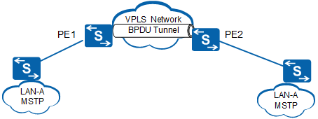
Configure Layer 2 protocol tunneling on interfaces of PEs connected to user network devices and configure PEs to replace the multicast MAC address of Layer 2 protocol packets with the specified multicast MAC address.
Bind user-side interfaces to the same L2VPN so that Layer 2 protocol packets can be transparently transmitted on the backbone network through the L2VPN tunnel.