LDP FRR
LDP fast reroute (FRR) provides link backup on an MPLS network. When the primary LSP fails, traffic is quickly switched to the backup LSP, minimizing traffic loss.
Background
On an MPLS network, when the primary link fails, IP FRR ensures fast IGP route convergence and switches traffic to the backup link. However, a new LSP needs to be established, which causes traffic loss. If the LSP fails (for some reason other than a primary link failure), traffic is restored until a new LSP is established, causing traffic interruption for a long time. LDP FRR is used on an MPLS network to address these issues.
LDP FRR, using the liberal label retention mode of LDP, obtains a liberal label, assigns a forwarding entry to the label, and delivers the forwarding entry to the forwarding plane as the backup forwarding entry for the primary LSP. When the interface goes Down (detected by the interface itself or by BFD) or the primary LSP fails (detected by BFD), traffic is quickly switched to the backup LSP.
Concepts
Manual LDP FRR: The outbound interface and next hop of the backup LSP must be specified using a command. When the source of the liberal label matches the outbound interface and next hop, a backup LSP can be established and its forwarding entry can be delivered.
Auto LDP FRR: This automatic approach depends on IP FRR. A backup LSP can be established and its forwarding entry can be delivered only when the source of the liberal label matches the backup route. That is, the liberal label is obtained from the outbound interface and next hop of the backup route, the backup LSP triggering conditions are met, and there is no backup LSP manually configured based on the backup route. By default, LDP LSP setup is triggered by a 32-bit backup route.
When both Manual LDP FRR and Auto LDP FRR meet the establishment conditions, Manual LDP FRR backup LSP is established preferentially.
Implementation
In liberal label retention mode, an LSR can receive a Label Mapping message of an FEC from any neighboring LSR. However, only the Label Mapping message sent by the next hop of the FEC can be used to generate a label forwarding table for LSP setup. In contrast, LDP FRR can generate an LSP as the backup of the primary LSP based on Label Mapping messages that are not from the next hop of the FEC. Auto LDP FRR establishes a forwarding entry for the backup LSP and adds the forwarding entry to the forwarding table. If the primary LSP fails, traffic is switched to the backup LSP quickly to minimize traffic loss.
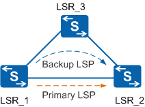
In Figure 1, the optimal route from LSR_1 to LSR_2 is LSR_1-LSR_2. A suboptimal route is LSR_1-LSR_3-LSR_2. After receiving a label from LSR_3, LSR_1 compares the label with the route from LSR_1 to LSR_2. Because LSR_3 is not the next hop of the route from LSR_1 to LSR_2, LSR_1 stores the label as a liberal label. If a route is available for the source of the liberal label, LSR_1 assigns a forwarding entry to the liberal label as the backup forwarding entry, and then delivers this forwarding entry to the forwarding plane with the primary LSP. In this way, the primary LSP is associated with the backup LSP.
LDP FRR is triggered when an interface failure is detected by the interface itself or BFD, or a primary LSP failure is detected by BFD. After LDP FRR is complete, traffic is switched to the backup LSP using the backup forwarding entry. Then the route is converged from LSR_1-LSR_2 to LSR_1-LSR_3-LSR_2. An LSP is established on the new path (the original backup LSP) and the original primary LSP is deleted. Traffic is forwarded along the new LSP of LSR_1-LSR_3-LSR_2.
Usage Scenario
Figure 1 shows a typical application environment of LDP FRR. LDP FRR functions well in a triangle topology but may not take effect in some situations in a rectangle topology.
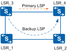
As shown in Figure 2, if the optimal route from LSR_1 to LSR_4 is LSR_1-LSR_2-LSR_4 (with no other route for load balancing), LSR_3 receives a liberal label from LSR_1 and is bound to LDP FRR. If the link between LSR_3 and LSR_4 fails, traffic is switched to the route of LSR_3-LSR_1-LSR_2-LSR_4. No loop occurs in this situation.
However, if optional routes from LSR_1 to LSR_4 are available for load balancing (LSR_1-LSR_2-LSR_4 and LSR_1-LSR_3-LSR_4), LSR_3 may not receive a liberal label from LSR_1 because LSR_3 is a downstream node of LSR_1. Even if LSR_3 receives a liberal label and is configured with LDP FRR, traffic may still be forwarded to LSR_3 after the traffic switching, leading to a loop. The loop exists until the route from LSR_1 to LSR_4 is converged to LSR_1-LSR_2-LSR_4.