TE FRR
Traffic engineering fast reroute (TE FRR) provides link protection and node protection for MPLS TE tunnels. If a link or node fails, TE FRR rapidly switches traffic to a backup path, minimizing traffic loss.
Background
A link or node failure triggers a primary/backup CR-LSP switchover. The switchover is not completed until the IGP routes of the backup path converge, CSPF calculates a new path, and a new CR-LSP is established. Traffic is lost during this process.
TE FRR technology can prevent traffic loss during a primary/backup CR-LSP switchover. After a link or node fails, TE FRR establishes a CR-LSP that bypasses the faulty link or node. The bypass CR-LSP can then rapidly take over traffic to minimize loss. At the same time, the ingress node reestablishes a primary CR-LSP.
Concepts
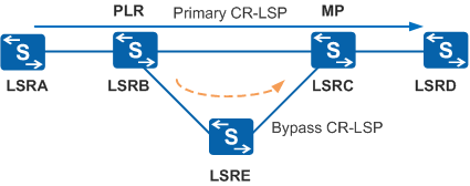
Table 1 explains the components shown in Figure 1.
Concept |
Description |
|---|---|
Primary CR-LSP |
Protected CR-LSP. |
Bypass CR-LSP |
CR-LSP protecting the primary CR-LSP. A bypass CR-LSP is usually in idle state and does not forward service traffics. If the bypass CR-LSP is required to forward service data, it must be assigned sufficient bandwidth. |
PLR |
Point of local repair, ingress node of a bypass CR-LSP. The PLR can be the ingress node but not the egress node of the primary CR-LSP. |
MP |
Merge point, egress node of a bypass CR-LSP. It must be on the path of the primary CR-LSP but cannot be the ingress node of the primary CR-LSP. |
Classified by |
Type |
Description |
|---|---|---|
Protected object |
Link protection |
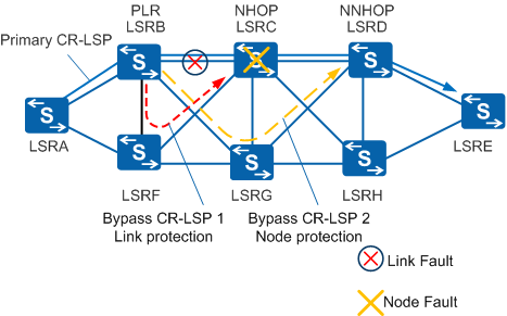
In Figure 2 below, the primary CR-LSP passes through the direct link between the PLR (LSRB) and MP (LSRC). Bypass LSP 1 can protect this link, which is called link protection. |
Node protection |
In Figure 2 below, the primary CR-LSP passes through LSRC between the PLR (LSRB) and MP (LSRD). Bypass LSP 2 can protect LSRC, which is called node protection. |
|
Bandwidth |
Bandwidth protection |
A bypass CR-LSP is assigned bandwidth higher than or equal to the primary CR-LSP bandwidth, so that the bypass CR-LSP protects the path and bandwidth of the primary CR-LSP. |
Non-bandwidth protection |
A bypass CR-LSP has no bandwidth and protects only the path of the primary CR-LSP. |
|
Implementation |
Manual protection |
A bypass CR-LSP is manually configured and bound to a primary CR-LSP. |
Auto protection |
An auto FRR-enabled node automatically establishes a bypass CR-LSP. The node binds the bypass CR-LSP to a primary CR-LSP if the node receives an FRR protection request and the FRR topology requirements are met. |


A bypass CR-LSP supports the combination of protection modes. For example, manual protection, node protection, and bandwidth protection can be implemented together on a bypass CR-LSP.
Implementation
TE FRR is implemented as follows:
Setup of a primary CR-LSP
A primary CR-LSP is set up in the same way as a common CR-LSP except that the ingress node adds flags into the SESSION_ATTRIBUTE object in a Path message. For example, the local protection desired flag indicates that the primary CR-LSP requires a bypass CR-LSP, and the bandwidth protection desired flag indicates that the primary CR-LSP requires bandwidth protection.
Binding between a bypass CR-LSP and the primary CR-LSP
FRR TE searches for a suitable bypass CR-LSP for the primary CR-LSP. A bypass CR-LSP can be bound to a primary CR-LSP only if the primary CR-LSP has a local protection desired flag. The binding process is completed before a CR-LSP switchover.
Before binding a bypass CR-LSP to a primary CR-LSP, the PLR must obtain the following from the Record Route Object (RRO) in the received Resv message: the outbound interface of the bypass CR-LSP, the next hop label forwarding entry (NHLFE), the label switching router (LSR) ID of the MP, the label allocated by the MP, and the protection type.
The PLR on the primary CR-LSP already knows its next hop (NHOP) and next NHOP (NNHOP). If the egress LSR ID of the bypass CR-LSP is the same as the NHOP LSR ID, the bypass CR-LSP provides link protection. If the egress LSR ID of the bypass CR-LSP is the same as the NNHOP LSR ID, the bypass CR-LSP provides node protection. In Figure 3, bypass LSP 1 protects the link between LSRB and LSRC, and bypass LSP 2 protects the node between LSRB and LSRD.If multiple bypass CR-LSPs are established, the PLR checks whether the bypass CR-LSP protect bandwidth, their implementations, and protected objects in sequence. Bypass CR-LSPs providing bandwidth protection are preferred over those that do not provide bandwidth protection. Manual bypass CR-LSPs are preferred over auto bypass CR-LSPs. Bypass CR-LSPs providing node protection are preferred over those providing link protection. Figure 3 shows two bypass CR-LSPs. If both the bypass CR-LSPs provide bandwidth protection and are manually configured, bypass LSP 2 is bound to the primary CR-LSP. (Bypass LSP 2 provides node protection, and bypass LSP 1 provides link protection.) If bypass LSP 1 provides bandwidth protection but bypass LSP 2 does not, bypass LSP 1 is bound to the primary CR-LSP.
After the binding is complete, the primary CR-LSP's NHLFE records the bypass CR-LSP's NHLFE index and an inner label that the MP allocates to the upstream node on the primary CR-LSP. This label is used to forward traffic during a primary/backup CR-LSP switchover.
Fault detection
- Link protection uses a link layer protocol to detect and report faults. The speed of fault detection at the link layer depends on the link type.
- Node protection uses a link layer protocol to detect link faults. If no fault occurs on a link, RSVP Hello or BFD for RSVP is used to detect faults on the protected node.
As soon as a link or node fault is detected, an FRR switchover is triggered. In node protection, only the link between the protected node and the PLR is protected. The PLR cannot detect faults on the link between the protected node and the MP.
Link fault detection, BFD, and RSVP Hello mechanisms detect a failure at descending speeds.
Switchover
When the primary CR-LSP fails, service traffic and RSVP messages are switched to the bypass CR-LSP, and the switchover event is advertised to the upstream nodes. Upon receiving a data packet, the PLR pushes an inner label and an outer label into the packet. The inner label is allocated by the MP to the upstream node on the primary CR-LSP, and the outer label is allocated by the next hop on the bypass CR-LSP to the PLR. The penultimate hop of the bypass CR-LSP pops the outer label and forwards the packet with only the inner label to the MP. The MP forwards the packet to the next hop along the primary CR-LSP according to the inner label.
Figure 4 shows nodes on the primary and bypass CR-LSPs, labels allocated to the nodes, and behavior that the nodes perform. The bypass CR-LSP provides node protection. If LSRC or the link between LSRB and LSRC fails, the PLR (LSRB) swaps the inner label 1024 to 1022, pushes the outer label 34 into a packet, and forwards the packet to the next hop along the bypass CR-LSP. The lower part of Figure 4 shows the packet forwarding process after a TE FRR switchover.Switchback
After a TE FRR switchover is complete, the ingress node of the primary CR-LSP reestablishes the primary CR-LSP using the make-before-break mechanism. Service traffic and RSVP messages are switched back to the primary CR-LSP after the primary CR-LSP is successfully reestablished. The reestablished primary CR-LSP is called a modified CR-LSP. The make-before-break mechanism allows the original primary CR-LSP to be torn down only after the modified CR-LSP is set up successfully.

FRR does not take effect if multiple nodes fail simultaneously. After data is switched from the primary CR-LSP to the bypass CR-LSP, the bypass CR-LSP must remain Up to ensure data forwarding. If the bypass CR-LSP fails, the protected data cannot be forwarded using MPLS, and the FRR function fails. Even if the bypass CR-LSP is reestablished, it cannot forward data. Data forwarding will be restored only after the primary CR-LSP restores or is reestablished.
Other Functions
N:1 protection
TE FRR supports N:1 protection mode, in which a bypass CR-LSP protects multiple primary CR-LSPs.
Cooperation Between CR-LSP Backup and TE FRR
Combination of CR-LSP backup and TE FRR
CR-LSP ordinary backup and TE FRR: TE FRR can rapidly detect a link failure and switch traffic to the bypass CR-LSP. When both primary and bypass CR-LSPs fail, a backup CR-LSP is established to take over traffic.
CR-LSP hot standby and TE FRR: TE FRR can rapidly detect a link failure and switch traffic to the bypass CR-LSP. Link failure information is then sent to the tunnel ingress node through a signaling protocol and traffic is switched to a backup CR-LSP.
Association between CR-LSP backup and TE FRR
After TE FRR local protection and backup CR-LSP end-to-end protection are deployed, the system supports associated protection of bypass and backup CR-LSPs. After association between CR-LSP backup and TE FRR is enabled:
If CR-LSP ordinary backup is enabled, the following situations occur:
When the protected link or node fails, TE FRR switches traffic to the bypass CR-LSP and attempts to restore the primary CR-LSP and to set up a backup CR-LSP.
After the backup CR-LSP is set up successfully but the primary CR-LSP has not restored, traffic is switched to the backup CR-LSP.
After the primary CR-LSP restores successfully, traffic is switched back to the primary CR-LSP, regardless of whether traffic is transmitted along the bypass or backup CR-LSP.
If the backup CR-LSP fails to be set up and the primary CR-LSP is not restored, traffic is transmitted along the bypass CR-LSP.
If CR-LSP hot standby is enabled, the following situations occur:
When the protected link or node fails and the backup CR-LSP is Up, traffic is switched to the bypass CR-LSP and then immediately to the backup CR-LSP. At the same time, the ingress node attempts to restore the primary CR-LSP.
If the backup CR-LSP is Down, traffic is switched in the same manner as in ordinary backup mode.
In CR-LSP hot standby mode, the ingress node attempts to set up a backup CR-LSP while the primary CR-LSP is Up. After the backup CR-LSP is created successfully, more bandwidth is occupied. In CR-LSP ordinary backup mode, the ingress node starts to set up a backup CR-LSP only when the primary CR-LSP is in FRR-in-use state. No more bandwidth is occupied when the primary CR-LSP is working properly. Therefore, association between CR-LSP ordinary backup and TE FRR is recommended.