MPLS Forwarding
MPLS Forwarding Process
Basic Concepts
Label operations involved in MPLS packet forwarding include push, swap, and pop:
Push: When an IP packet enters an MPLS domain, the ingress node adds a new label to the packet between the Layer 2 header and the IP header. Alternatively, an LSR adds a new label to the top of the label stack.
Swap: When a packet is transferred within the MPLS domain, a local node swaps the label at the top of the label stack in the MPLS packet for the label allocated by the next hop according to the label forwarding table.
Pop: When a packet leaves the MPLS domain, the label is popped out of (removed from) the MPLS packet.
A label is invalid at the last hop of an MPLS domain. The penultimate hop popping (PHP) feature applies. On the penultimate node, the label is popped out of the packet to reduce the size of the packet that is forwarded to the last hop. Then, the last hop directly forwards the IP packet or forwards the packet by using the second label.
By default, PHP is configured on the egress node. The egress node supporting PHP allocates the label with the value of 3 to the penultimate hop.
Basic Forwarding Process
LSPs that support PHP are used in the following example to describe how MPLS packets are forwarded.
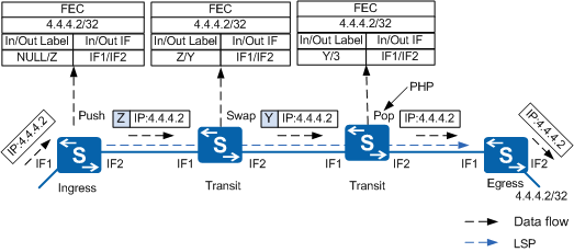
As shown in Figure 1, the LSRs have distributed MPLS labels and set up an LSP with the destination address of 4.4.4.2/32. MPLS packets are forwarded as follows:
The ingress node receives an IP packet destined for 4.4.4.2. Then, the ingress node adds Label Z to the packet and forwards it.
When the downstream transit node receives the labeled packet, the node replaces Label Z by Label Y.
When the transit node at the penultimate hop receives the packet with Label Y, the node pops out Label Y because the label value is 3. The transit node then forwards the packet to the egress node as an IP packet.
The egress node receives the IP packet and forwards it to 4.4.4.2/32.
Detailed MPLS Packet Forwarding Process
Basic Concepts
The following entities are used in MPLS packet forwarding:
Tunnel ID
Each tunnel is assigned a unique ID to ensure that upper layer applications (such as VPN and route management) on a tunnel use the same interface. The tunnel ID is 32 bits long and is valid only on the local end.
NHLFE
A next hop label forwarding entry (NHLFE) is used to guide MPLS packet forwarding.
An NHLFE specifies the tunnel ID, outbound interface, next hop, outgoing label, and label operation.
FEC-to-NHLFE (FTN) maps each FEC to a group of NHLFEs. An FTN can be obtained by searching for tunnel IDs that are not 0x0 in a FIB. The FTN is available on the ingress only.
ILM
The incoming label map (ILM) maps each incoming label to a group of NHLFEs.
The ILM specifies the tunnel ID, incoming label, inbound interface, and label operation.
The ILM on a transit node identifies bindings between labels and NHLFEs. Similar a FIB that provides forwarding information based on destination IP addresses, the ILM provides forwarding information based on labels.
Detailed Forwarding Process
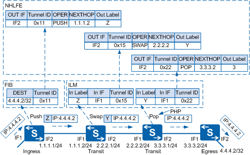
Figure 2 shows the detailed MPLS packet forwarding process.
When an IP packet enters an MPLS domain, the ingress node searches the FIB to check whether the tunnel ID matching the destination IP address is 0x0.
If the tunnel ID is 0x0, the packet is forwarded along the IP link.
If the tunnel ID is not 0x0, the packet is forwarded along an LSP.
During MPLS forwarding, LSRs find the matching FIB entries, ILM entries, and NHLFEs for MPLS packets based on tunnel IDs.
The ingress node processes MPLS packets as follows:
Searches the FIB to find the tunnel ID matching the destination IP address.
Finds the NHLFE matching the tunnel ID in the FIB and associates the FIB entry with the NHLFE entry.
Checks the NHLFE to obtain the outbound interface, next hop, outgoing label, and label operation.
Pushes the label into IP packets, processes the EXP field according to QoS policy, and processes the TTL field, and then sends the encapsulated MPLS packets to the next hop.

For details on how the ingress node processes the EXP field and TTL field, see Understanding MPLS QoS in the MPLS QoS Configuration and Processing MPLS TTL.
A transit node processes MPLS packets as follows:
Finds the ILM matching the MPLS label to obtain the Tunnel ID.
Finds the NHLFE matching the Tunnel ID in the ILM.
Checks the NHLFE to obtain the outbound interface, next hop, outgoing label, and label operation.
Processes the MPLS packets according to the label value:
If the label value is greater than or equal to 16, the transit node replaces the label with a new label replaces and processes the EXP field and TTL field. After that, the transit node forwards the MPLS packet with the new label to the next hop.
If the label value is 3, the transit node pops out the label and processes the EXP field and TTL field. After that, the transit node forwards the packets through an IP route or based on the next layer label.
The egress node forwards MPLS packets based on the ILM and forwards IP packets based on the routing table
When the egress node receives IP packets, it checks the FIB and performs IP forwarding.
When the egress node receives MPLS packets, it checks the ILM for the label operation and processes the EXP field and TTL field.
When the S flag in the label is 1, the label is at the bottom of the label stack, and the packet is directly forwarded through an IP route.
When the S field in the label is 0, a next-layer label exists, and the packet is forwarded based on the next layer label.
MPLS TTL Processing
This section describes how MPLS processes the TTL and responds to TTL timeout.
MPLS TTL Processing Modes
The TTL field in an MPLS label is 8 bits long. The TTL field is the same as that in an IP packet header. MPLS processes the TTL to prevent loops and implement traceroute.
RFC 3443 defines two modes in which MPLS can process the TTL in MPLS packets: Uniform and Pipe modes. By default, MPLS processes the TTL in Uniform mode. The two modes work as follows:
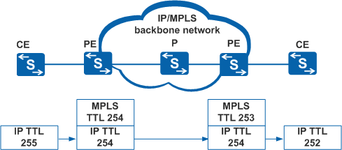
Uniform mode
When IP packets enter an MPLS network, the ingress node decreases the IP TTL by one and copies this new value to the MPLS TTL field. The TTL field in MPLS packets is processed in standard mode. The egress node decreases the MPLS TTL by one and maps this new value to the IP TTL field. Figure 3 shows how the TTL field is processed on the transmission path.
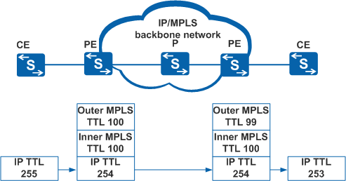
Pipe mode
As shown in Figure 4, the ingress node decreases the IP TTL by one and the MPLS TTL remains constant. The TTL field in MPLS packets is processed in standard mode. The egress node decreases the IP TTL by one. In Pipe mode, the IP TTL only decreases by one on the ingress node and one on the egress node when packets travel across an MPLS network.
In MPLS VPN applications, the MPLS backbone network needs to be shielded to ensure network security. The Pipe mode is recommended for private network packets.
ICMP Response Packet
On an MPLS network, when an LSR receives an MPLS packet with the TTL value of 1, the LSR generates an Internet Control Message Protocol (ICMP) response packet.
- If the LSR has a reachable route to the sender, the LSR directly sends the ICMP response packet to the sender through the IP route.
- If the LSR has no reachable route to the sender, the LSR forwards the ICMP response packet along the LSP. The egress node forwards the ICMP response packet to the sender.
In most cases, the received MPLS packet contains only one label and the LSR responds to the sender with the ICMP response packet using the first method. If the MPLS packet contains multiple labels, the LSR uses the second method.
The MPLS VPN packets may contain only one label when they arrive at an autonomous system boundary router (ASBR) on the MPLS VPN. These devices have no IP routes to the sender, so they use the second method to reply to the ICMP response packets.