LSP Connectivity Check
Introduction to LSP Connectivity Check
On an MPLS network, the control panel used for setting up an LSP cannot detect the failure in data forwarding of the LSP. This makes network maintenance difficult. The MPLS ping and tracert mechanisms detect LSP errors and locate faulty nodes.
MPLS ping is used to check network connectivity. MPLS tracert is used to check the network connectivity, and to locate network faults. Similar to IP ping and tracert, MPLS ping and tracert use MPLS echo request packets and MPLS echo reply packets to check LSP availability. MPLS echo request packets and echo reply packets are both encapsulated into User Datagram Protocol (UDP) packets. The UDP port number of the MPLS echo request packet is 3503, which can be identified only by MPLS-enabled devices.
An MPLS echo request packet carries FEC information to be detected, and is sent along the same LSP as other packets with the same FEC. In this manner, the connectivity of the LSP is checked. MPLS echo request packets are forwarded to the destination end using MPLS, while MPLS echo reply packets are forwarded to the source end using IP. Routers set the destination address in the IP header of the MPLS echo request packets to 127.0.0.1/8 (local loopback address) and the TTL value is 1. In this way, MPLS echo request packets are not forwarded using IP forwarding when the LSP fails so that the failure of the LPS can be detected.
MPLS Ping
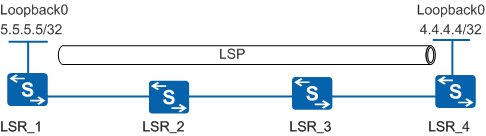
As shown in Figure 1, LSR_1 establishes an LSP to LSR_4. LSR_1 performs MPLS ping on the LSP by performing the following steps:
- LSR_1 checks whether the LSP exists. (On a TE tunnel, the router checks whether the tunnel interface exists and the CR-LSP has been established.) If the LSP does not exist, an error message is displayed and the MPLS ping stops. If the LSP exists, LSR_1 performs the following operations.
- LSR_1 creates an MPLS echo request packet and adds 4.4.4.4 to the destination FEC in the packet. In the IP header of the MPLS echo request packet, the destination address is 127.0.0.1/8 and the TTL value is 1. LSR_1 searches for the corresponding LSP, adds the LSP label to the MPLS echo request packet, and sends the packet to LSR_2.
- Transit nodes LSR_2 and LSR_3 forward the MPLS echo request packet based on MPLS. If MPLS forwarding on a transit node fails, the transit node returns an MPLS echo reply packet carrying the error code to LSR_1.
- If no fault exists along the MPLS forwarding path, the MPLS echo request packet reaches the LSP egress node LSR_4. LSR_4 returns a correct MPLS echo reply packet after verifying that the destination IP address 4.4.4.4 is the loopback interface address. MPLS ping is complete.
MPLS Tracert
As shown in Figure 1, LSR_1 performs MPLS tracert on LSR_4 (4.4.4.4/32) by performing the following steps:
- LSR_1 checks whether an LSP exists to LSR_4. (On a TE tunnel, the router checks whether the tunnel interface exists and the CR-LSP has been established.) If the LSP does not exist, an error message is displayed and the tracert stops. If the LSP exists, LSR_1 performs the following operations.
- LSR_1 creates an MPLS echo request packet and adds 4.4.4.4 to the destination FEC in the packet. In the IP header of the MPLS echo request packet, the destination address is 127.0.0.1/8. Then LSR_1 adds the LSP label to the packet, sets the MPLS TTL value to 1, and sends the packet to LSR_2. The MPLS echo request packet contains a downstream mapping type-length-value (TLV) that carries downstream information about the LSP at the current node, such as next-hop address and outgoing label.
- Upon receiving the MPLS echo request packet, LSR_2 decreases the MPLS TTL by one and finds that TTL times out. LSR_2 then checks whether the LSP exists and the next-hop address and whether the outgoing label of the downstream mapping TLV in the packet is correct. If so, LSR_2 returns a correct MPLS echo reply packet that carries the downstream mapping TLV of LSR_2. If not, LSR_2 returns an incorrect MPLS echo reply packet.
- After receiving the correct MPLS echo reply packet, LSR_1 resends the MPLS echo request packet that is encapsulated in the same way as step 2 and sets the MPLS TTL value to 2. The downstream mapping TLV of this MPLS echo request packet is replicated from the MPLS echo reply packet. LSR_2 performs common MPLS forwarding on this MPLS echo request packet. If TTL times out when LSR_3 receives the MPLS echo request packet, LSR_3 processes the MPLS echo request packet and returns an MPLS echo reply packet in the same way as step 3.
- After receiving a correct MPLS echo reply packet, LSR_1 repeats step 4, sets the MPLS TTL value to 3, replicates the downstream mapping TLV in the MPLS echo reply packet, and sends the MPLS echo request packet. LSR_2 and LSR_3 perform common MPLS forwarding on this MPLS echo request packet. Upon receiving the MPLS echo request packet, LSR_4 repeats step 3 and verifies that the destination IP address 4.4.4.4 is the loopback interface address. LSR_4 returns an MPLS echo reply packet that does not carry the downstream mapping TLV. MPLS tracert is complete.
When routers return the MPLS echo reply packet that carries the downstream mapping TLV, LSR_1 obtains information about each node along the LSP.