Operating Modes
Unicast Server/Client Mode
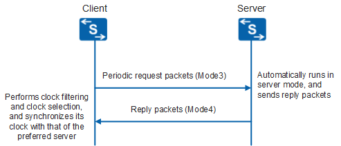
Within a synchronous subnet, unicast server/client mode runs on a higher stratum. In this mode, devices are required to obtain the server IP address in advance. In unicast, hosts running in client or server mode perform the following functions:
Client
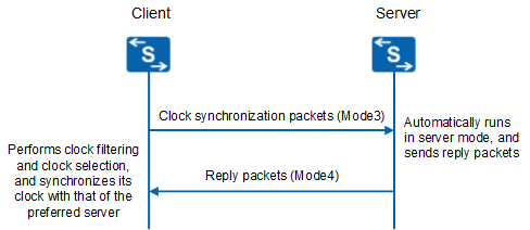
Hosts running in client mode will periodically send packets to the server. The Mode field of the packets has a value of 3. This indicates that the packets are being sent by a client. Upon receiving a reply packet, the client filters clock signals. It then selects usable clock signals, and synchronizes its clock with the server providing the optimal clock. A client will not verify the reachability and stratum of the server. Typically, a host running in client mode is a workstation within a network. Clock synchronization is performed between the client and the server but the server clock is not altered.
Server
Hosts running in server mode receive packets from clients and then reply to these packets. The Mode field in reply packets has a value of 4. This indicates that the packets are being sent from a server. Typically, a host running in server mode is a clock server within a network. Server mode hosts provide synchronization information for clients but do not alter their own clocks.
- Swap the position of destination IP address and source IP address.
- Swap the position of source port number and destination port number.
- Fill in the necessary information.
- Send the message to the client.
Peer Mode
In peer mode, active and passive peers perform the following functions:
Active peer
A host that functions as an active peer will periodically send packets. The value of the Mode field in a packet has a value of 1. This indicates that the packet was sent by an active peer, without consideration for whether peers are reachable and stratum of peers. Active peers can provide time information about the local clock to peers. They may also synchronize time information of the local clock based on that of the peer clock.
Passive peer
A host that functions as a passive peer will receive packets from the active peer and send reply packets. The value of the Mode field in a reply packet has a value of 2. This indicates that the packet was sent by a passive peer. Passive peers can provide time information about the local clock to peers. They may also synchronize time information of the local clock based on that of the peer clock.
The peer mode operates on a lower stratum within a synchronous subnet. In peer mode, an active peer and a passive peer can synchronize with each other. The peer with the higher stratum (a lower level) synchronizes with the peer with a lower stratum (a higher level).
Before devices enter the peer mode, the following occurs:
- Active peers in this mode send NTP packets. The Mode field will have a value of 3 (the client mode).
- Passive peers respond with NTP packets. The Mode field will have a value of 4 (the server mode).
This interaction will create a network delay, allowing devices at both ends to enter the peer mode.


The passive peer does not require configuration. A host establishes a connection and sets relevant state variables only after receiving an NTP packet.
Broadcast Mode
Broadcast mode is applied to a high-speed network that has multiple workstations, but only when the network does not require high precision. In typical scenarios, one or more clock servers on a network will periodically send broadcast packets to the workstations. The delay of packet transmission within a LAN is measured at the millisecond level. In broadcast mode, clients and servers perform the following functions:
Broadcast server
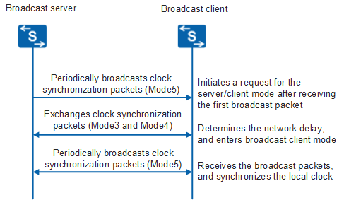
A host running in broadcast mode will send clock synchronization packets to the broadcast address 255.255.255.255 periodically. The Mode field in a packet has a value of 5. This indicates that the packet was sent by a host running in broadcast or multicast mode, without considering whether peers are reachable and on which stratum the peers are located. Hosts running in broadcast mode are typically clock servers running high-speed broadcast media over networks. They provide synchronization information to all peers, but do not alter their own clocks.
Broadcast client
Clients process clock synchronization packets received from the server. When the first clock synchronization packet is received by the client, the client and server exchange NTP packets with Mode fields which have a value of 3 (sent by the client). They will also exchange NTP packets with Mode fields which have a value of 4 (sent by the server). During this process, the client enables server/client mode for a short time, allowing information exchange with the remote server. This allows the client to determine the network delay between client and server. Following this, the client returns to broadcast mode, resuming analysis of incoming clock synchronization packets and synchronizing the local clock.
Multicast Mode
Multicast mode is used when a significant number of clients are distributed throughout a network. This normally results in large number of NTP packets in the network. In multicast mode, a single NTP multicast packet can potentially reach all the clients on the network and reduce the control traffic on the network.
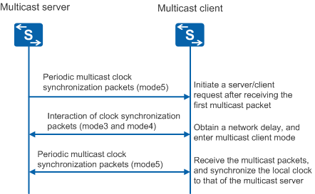
Multicast server: A server running in multicast mode sends clock synchronization packets to a multicast address periodically. The value of the Mode field in a packet is set to 5. This indicates that the packet is sent by a host that runs in broadcast or multicast mode. The host running in multicast mode is usually a clock server running high-speed broadcast media on the network, which provides synchronization information for all of its peers but does not alter the clock of its own.
Multicast client: The client listens to the multicast packets from the server. When the client receives the first broadcast packet, the client and server exchange NTP packets whose values of Mode fields are 3 (sent by the client) and the NTP packets whose values of Mode fields are 4 (sent by the server). In this process, the client enables the server/client mode for a short time to exchange information with the remote server. This allows the client to obtain the network delay between the client and the server. Then, the client returns the multicast mode, and continues to sense the incoming multicast packets to synchronize the local clock.
Manycast Mode
Manycast mode is applied when a small set of servers are scattered throughout a network. Clients are able to discover and then synchronize with the closest manycast server. Manycast is especially useful when the server frequently changes, which will cause reconfigurations of all clients within the network.
Manycast server
The manycast server continuously analyzes incoming packets. If server synchronization is possible, the server will return a packet with the Mode field set to 4 using the unicast address of the client as the destination address.
Manycast client
The manycast client periodically sends request packets with the Mode field set to 3 to an IPv4/IPv6 multicast address. After receiving a reply packet, the client filters and selects clock signals, and then synchronizes its clock with the server which provides the optimal clock.
- When the client sends an NTP packet, the TTL of the packet increases from the initial value of 1.
- TTL increases until either the minimum number of connections is reached or the TTL value reaches the upper limit, 255.
- If the TTL reaches the upper limit or the number of connections reaches the minimum number, the client stops data transmission in a timeout period, eliminating all connections. This occurs only if the synchronization process cannot be completed by the client.
- The client repeats the preceding process until synchronization occurs.
In NTP implementation, a peer structure is established for each synchronization source. These peer structures are stored as a chain in Hash form. Each peer structure corresponds to a connection.