Implementation of a Single RRPP Ring (When the Fault is Rectified)
Implementation of a Single RRPP Ring
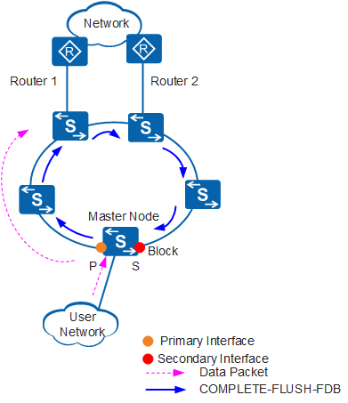
In Figure 1:
When the faulty interface on a transit node recovers, the transit node enters the Preforwarding state and blocks the recovered interface.
After all the failed links on the ring recover, the secondary interface on the master node receives the Hello packets sent from the primary interface.
When receiving the Hello packets, the master node enters the Complete state and blocks the secondary interface.
The master node sends a Complete-Flush-FDB packet from the primary interface to request that all transit nodes update forwarding entries.
When receiving the Complete-Flush-FDB packet, the transit node enters the LinkUp state, unblocks the temporarily blocked interface, and updates forwarding entries.
Fault Rectification Detection and Processing
When the primary interface on a transit node changes to Up, the master node does not immediately detect the change and the secondary interface remains unblocked. If the transit node immediately switches back to the LinkUp state, a temporary loop caused by data packets occurs on the ring. To prevent such loops, the transit node immediately blocks the recovered interfaces and enters the Preforwarding state when the primary and secondary interfaces on the transit node recover. However, the ring does not recover because ring recovery is initiated by the master node. When all links on the ring are Up and the secondary interface on the master node can receive the Hello packets sent by the primary interface on the master node, the master node enters the Complete state.
When the network topology changes, the master node must update the MAC address entries and ARP entries. The master node must also send a Common-Flush-FDB packet from the primary interface to request that all transit nodes update their MAC address entries and ARP entries. Upon receiving the Complete-Flush-FDB packet from the master node, the transit nodes in Preforwarding state enter the LinkUp state.
If the Complete-Flush-FDB packet is lost during transmission, a backup mechanism is used to unblock the temporarily blocked interfaces on transit nodes. If a transit node is in Preforwarding state, the transit node unblocks the temporarily blocked interfaces when receiving no Complete-Flush-FDB packet from the master node in the period specified by the Fail timer. The transit node then updates its MAC address entries and ARP entries to recover data communication.
LinkUp Timer
After the link recovers, traffic transmission paths are switched frequently if the link status changes frequently on a ring. As a result, loop flapping occurs and system performance deteriorates. To address this problem, a LinkUp timer is used to set the period after which the faulty master node enters the Complete state. This prevents transmission paths from changing frequently and reduces loop flapping impact on system performance.
If a LinkUp timer is configured, the master node does not immediately enter Complete state when its secondary interface receives a Hello message. Instead, the master node triggers the LinkUp timer and performs the following operations:
Before the LinkUp timer expires, the master node does not process the Hello message received from the secondary interface and the RRPP ring topology remains unchanged. If the link status changes (for example, the master node receives a LinkDown packet or the link goes Down) the timer is closed.
After the LinkUp timer expires, the master node processes the Hello message. The master node blocks its secondary interface and requests all transit nodes to update their forwarding entries. The RRPP ring is re-converged.
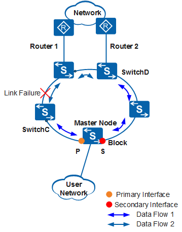
In Figure 2, traffic between SwitchC and SwitchD is forwarded along data flow 1 when the ring fails. After the fault is rectified, the RRPP ring recalculates the topology. Traffic between SwitchC and SwitchD is switched to data flow 2.
When no LinkUp timer is configured, if the recovered link is unstable and fails again, the RRPP ring recalculates the topology. Traffic between SwitchC and SwitchD is switched to data flow 1. This may cause frequent changes of traffic transmission paths. As a result, traffic is lost and system performance deteriorates.
When a LinkUp timer is configured, traffic is not switched immediately when the fault is rectified. If the recovered link fails again, traffic between SwitchC and SwitchD is still transmitted along data flow 1.