Cascading of Smart Link and Monitor Link
Figure 1 shows cascading of Smart Link and Monitor Link, in which a Smart Link group can function as the uplink interface of a Monitor Link group. This networking provides enhanced reliability in link backup.
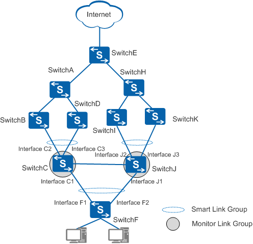
In Figure 1, the uplink interfaces on SwitchC and SwitchJ are added to Smart Link groups to guarantee reliability. Monitor Link groups are configured on SwitchC and SwitchJ, with the Smart Link groups serving as uplink interfaces. An active/standby switchover will be triggered on SwitchF only if both the two uplink interfaces in a Smart Link group are Down.
Switch |
Smart Link Group |
Monitor Link Group |
||
|---|---|---|---|---|
Master Interface |
Slave Interface |
Uplink Interface |
Downlink Interface |
|
SwitchC |
Interface C2 |
Interface C3 |
Smart Link group Interface C2, Interface C3 |
Interface C1 |
SwitchJ |
Interface J2 |
Interface J3 |
Smart Link group Interface J2, Interface J3 |
Interface J1 |
SwitchF |
Interface F1 |
Interface F2 |
No Monitor Link group configured |
|