Smart Link Fundamentals
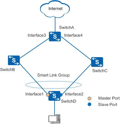
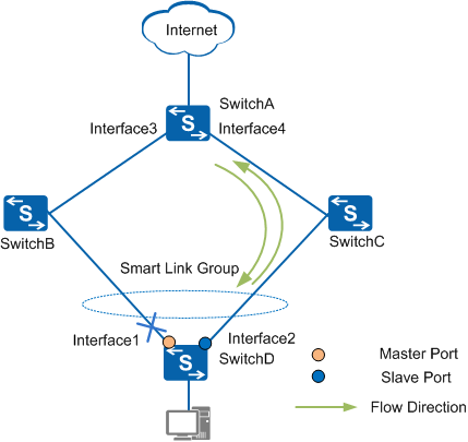
This section describes how Smart Link works when both links in a Smart Link group are working normally, one link fails, and the link recovers. Figure 1 illustrates an example network.
Both Links Are Working Properly
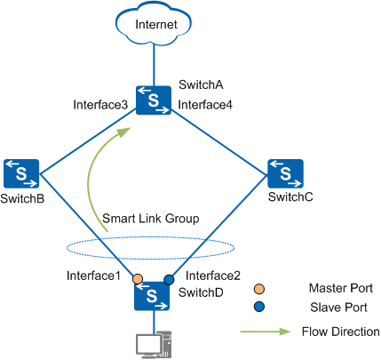
A Smart Link group configured on SwitchD contains Interface1 (master) and Interface2 (slave). When both uplinks are working normally, the master interface is in active state and its link is the primary link; the slave interface is in inactive state and its link is the backup link. As shown in Figure 2, data traffic is transmitted along the primary link. No loop exists on the network, so broadcast storms will not occur.
Primary Link Fails
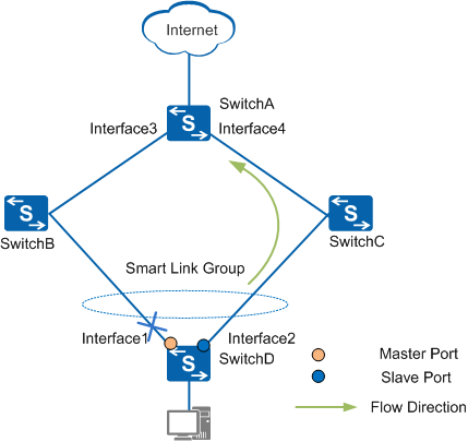
As shown in Figure 3, when the primary link on SwitchD fails, the master interface (Interface1) becomes inactive, and the slave interface (Interface2) becomes active. Existing MAC address entries and ARP entries on the switches no longer apply to the network. A mechanism is required to update MAC address entries and ARP entries. Two mechanisms are available: Flush packet-triggered and traffic-triggered automatic update.
Entry update triggered by Flush Packets
This mechanism is applicable when the upstream devices (SwitchA, SwitchB, and SwitchC in Figure 3) support the Smart Link function. To implement fast switchover, enable SwitchD to send Flush packets and enable Flush packet processing on all upstream device interfaces on the links.
- After a link switchover occurs on SwitchD, SwitchD sends a Flush packet over the new primary link (Interface2).
- When an upstream switch receives the Flush packet, it checks whether the control VLAN carried in the packet is included in the list of control VLANs for receiving Flush packets configured on the interface. If so, the switch processes the Flush packet and updates MAC address entries and ARP entries. If not, the device directly forwards the Flush packet upstream.
When SwitchA receives a data packet destined for SwitchD, SwitchA forwards this packet based on updated MAC address entries or ARP entries.
Automatic entry update triggered by traffic
This mechanism is applicable when upstream devices (including non-Huawei devices) do not support the Smart Link function. These devices update MAC address entries and ARP entries when they receive upstream traffic.
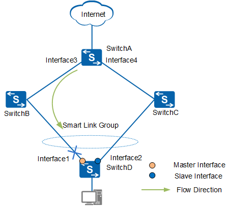
In Figure 4, if SwitchD does not send upstream traffic after the primary link fails, SwitchA does not update its MAC address entries or ARP entries. When SwitchA receives data packets destined for SwitchD, it still forwards the packets through Interface3, causing traffic loss. Traffic can be forwarded to SwitchD only after the original MAC address entries or ARP entries on SwitchA are aged out.
As shown in Figure 5, after the primary link fails, MAC address entries and ARP entries learned on Interface1 are deleted. If SwitchD needs to send upstream traffic, it must broadcast ARP packets first. When the upstream traffic arrives at Interface4 of SwitchA, SwitchA updates its MAC address entries and ARP entries. When SwitchA receives a data packet destined for SwitchD, it forwards this packet through Interface4. The packet is then forwarded to SwitchD through SwitchC.
Flush packets help improve entry update efficiency because upstream devices can update their MAC address entries and ARP entries before the entries are aged out. Generally, traffic is switched to the backup link in milliseconds, which minimizes traffic loss.
Primary Link Recovers
When the original primary link recovers, Interface1 remains blocked to ensure stable traffic transmission. To switch traffic back to the original primary link, use either of the following methods:
- Enable revertive switching on SwitchD. When the original primary link recovers, Smart Link waits until the WTR timer expires and then switches the traffic back to the original primary link.
- Manually switch the traffic back to the original primary link using the command line interface.
In Figure 1, revertive switching is enabled on SwitchD. When the link of Interface1 recovers, traffic is switched back to Interface1 after the WTR timer expires. When you run the manual traffic switching command, Interface2 is blocked and changes back to inactive state immediately, and Interface1 changes to active state.