MSTP Background
STP/RSTP Defect
Both STP and RSTP (which is an evolution of STP and allows for fast network topology convergence) suffer from a significant limitation: neither can implement VLAN-based load balancing because all VLANs on a LAN use one spanning tree. When a link is blocked, it no longer transmits traffic, which wastes bandwidth and prevents certain VLAN packets from being forwarded.
Figure 1 provides an example scenario where STP or RSTP is enabled on a LAN. In Figure 1, the broken line shows the spanning tree.
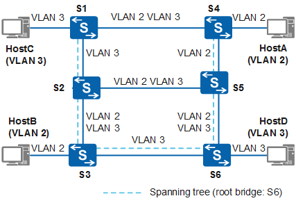
In Figure 1, S6 is the root switch. The links between S2 and S5 and between S1 and S4 are blocked. VLAN packets are transmitted through "VLAN 2" or "VLAN 3" links.
Because the link between S2 and S5 is blocked and the link between S3 and S6 denies packets from VLAN 2, HostA and HostB cannot communicate with each other despite both belonging to VLAN 2.
MSTP Improvements
Because the link between S2 and S5 is blocked and the link between S3 and S6 denies packets from VLAN 2, Host A and Host B cannot communicate with each other despite both belonging to VLAN 2.
To address the limitation of STP and RSTP, MSTP allows fast convergence and provides multiple paths to load balance VLAN traffic.
MSTP divides a switching network into multiple regions, each of which has multiple spanning trees that are independent of each other. Each spanning tree is called a Multiple Spanning Tree Instance (MSTI) and each region is called a Multiple Spanning Tree (MST) region. Figure 2 shows an example of an MST region.

An MSTI is a collection of VLANs. Binding multiple VLANs to a single MSTI reduces communication costs and resource usage. The topology of each MSTI is calculated independently, and traffic can be balanced among MSTIs. Multiple VLANs with the same topology can be mapped to a single MSTI. The forwarding state of the VLANs for a port is determined by the port state in the MSTI.
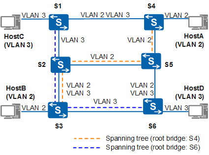
In Figure 2, MSTP maps VLANs to MSTIs in the VLAN mapping table. Each VLAN can be mapped to only one MSTI. This means that traffic of a VLAN can be transmitted in only one MSTI. An MSTI, however, can correspond to multiple VLANs.
- MSTI 1 uses S4 as the root switch to forward packets of VLAN 2.
- MSTI 2 uses S6 as the root switch to forward packets of VLAN 3.
In this situation, devices within the same VLAN can communicate with each other. Packets of different VLANs are load balanced along different paths.