Basic Concepts of MSTP
MSTP Network Hierarchy
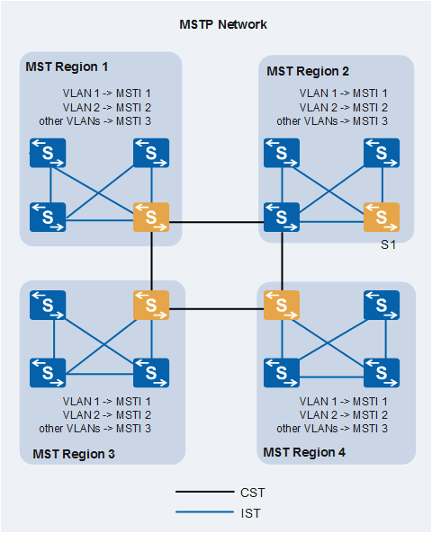
An MSTP network consists of one or more MST regions, each of which contains one or more MSTIs. An MSTI is a tree network that consists of switches running MSTP. Figure 1 provides an example of an MSTP network.
MST Region
- MSTP-enabled
- Same region name
- Same VLAN-MSTI mappings
- Same MSTP revision level
Multiple switches can be grouped into an MST region by using MSTP configuration commands.
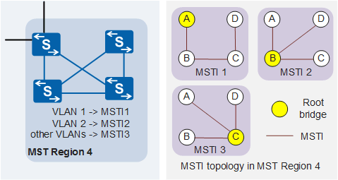
In Figure 2, MST region 4 contains SwitchA, SwitchB, SwitchC, and SwitchD, and has three MSTIs.
VLAN Mapping Table
Each MST region has a VLAN mapping table. The VLAN mapping table maps VLANs to MSTIs.
- VLAN 1 is mapped to MSTI 1.
- VLAN 2 is mapped to MSTI 2.
- Other VLANs are mapped to MSTI 3.
CST
A Common Spanning Tree (CST) connects all MST regions on a switching network.
The CST is calculated using STP or RSTP, with each MST region being considered as a single node.
In Figure 1, the regions that are connected through black lines form a CST.
IST
An Internal Spanning Tree (IST) resides within an MST region.
An IST is a special MSTI with an MSTI ID of 0.
An IST is a segment of the CIST in an MST region.
In Figure 1, the switches that are connected through dark blue lines in an MST region form an IST.
SST
- A switch running STP or RSTP belongs to only one spanning tree.
- An MST region has only one switch.
CIST
A Common and Internal Spanning Tree (CIST) connects all the switches on a switching network and is calculated using STP or RSTP.
In Figure 1, all ISTs and the CST form a CIST.
Regional Root
Regional roots are classified into Internal Spanning Tree (IST) and MSTI regional roots.
In Figure 1, the switches that are closest to the CIST root are IST regional roots.
An MST region can contain multiple spanning trees, each of which is called an MSTI. An MSTI regional root is the root of the MSTI. In Figure 2, each MSTI has its own regional root.
CIST Root
In Figure 1, the CIST root is the root bridge of the CIST. The CIST root is a device in S1.
Master Bridge
The master bridge is the switch closest to the CIST root in a region, for example, S1 in Figure 1.
If the CIST root is in an MST region, the CIST root is the master bridge of the region.
Port Roles
MSTP adds two extra port roles to those defined in RSTP. Table 1 describes the port roles included in MSTP.

Except edge ports, all ports participate in MSTP calculation.
A port can play different roles in different spanning tree instances.
Port Role |
Description |
|---|---|
Root port |
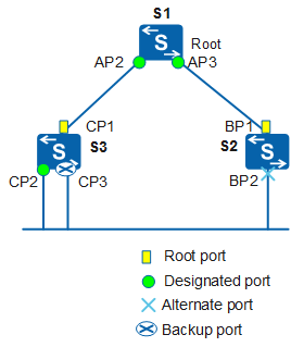
A root port sends data to a root bridge and is the port closest to the root bridge. Root bridges do not have root ports. Root ports are responsible for sending data to root bridges. In Figure 3, S1 is the root; CP1 is the root port on S3; BP1 is the root port on S2. |
Designated port |
The designated port on a switch forwards BPDUs to a downstream switch. In Figure 3, AP2 and AP3 are designated ports on S1; CP2 is a designated port on S3. |
Alternate port |
In Figure 3, BP2 is an alternate port. |
Backup port |
In Figure 3, CP3 is a backup port. |
Master port |
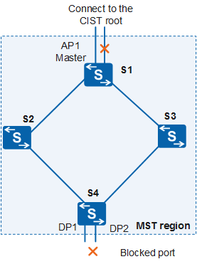
A master port is on the shortest path connecting MST regions to the CIST root. BPDUs of an MST region are sent to the CIST root through the master port. Master ports are special regional edge ports, functioning as root ports on ISTs or CISTs and master ports in instances. In Figure 4, S1, S2, S3, and S4 form an MST region. AP1 on S1 is the master port because it is the closest port in the region to the CIST root. |
Regional edge port |
A regional edge port is located at the edge of an MST region and connects to another MST region or an SST. In Figure 4, AP1, DP1, and DP2 in an MST region are directly connected to other regions. This means that they are all regional edge ports of the MST region. |
Edge port |
An edge port is located at the edge of an MST region and does not connect to any switching device. Generally, edge ports are directly connected to terminals. After MSTP is enabled on a port, edge port detection is started automatically. If the port fails to receive BPDU packets within (2 x Hello Timer + 1) seconds, the port is set to an edge port. Otherwise, the port is set to a non-edge port. |
MSTP Port States
Table 2 describes the MSTP port states, which are the same as those used in RSTP.
Port State |
Description |
|---|---|
Forwarding |
A port in this state can send and receive BPDUs. It can also forward user traffic. |
Learning |
A port in this state learns MAC addresses from user traffic to construct a MAC address table. In Learning state, the port can send and receive BPDUs, but cannot forward user traffic. |
Discarding |
A port in this state can send and receive BPDUs. |
Root, master, designated, and regional edge ports support all three port states. Alternate and backup ports support only the Discarding state.