How RSTP Achieves Rapid Convergence
Rapid Convergence Mechanisms
RSTP considers that the network topology has changed when a non-edge port transitions to the Forwarding state.
When detecting a topology change, RSTP devices react as follows:
- The local device starts a TC While timer on each non-edge designated port. The TC While timer value is twice the Hello timer value.
Within the TC While time, the local device deletes MAC address entries learned on ports whose states have changed. These ports send out RST BPDUs with the TC bit set to 1. When the TC While timer expires, the ports stop sending RST BPDUs.
- When other switches receive RST BPDUs, they clear MAC address entries learned on all their ports except the ports that receive the RST BPDUs. These switches also start a TC While timer on each non-edge designated port and repeat the preceding process.
In this manner, RST BPDUs are flooded on the network.
RSTP provides rapid convergence using the Proposal/Agreement Mechanism, Fast Switchover of the Root Port, and Edge Port.
Proposal/Agreement Mechanism
The Proposal/Agreement (P/A for short) mechanism enables a designated port to quickly transition to Forwarding state. In Figure 1, a new link is added between root bridge S1 and S2. On S2, p2 is an alternate port, p3 is a designated port in Forwarding state, and p4 is an edge port.
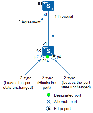
The proposal/agreement mechanism works as follows:
- p0 and p1 become designated ports and send RST BPDUs to each other.
- The RST BPDU sent from p0 is superior to that of p1. Therefore, p1 becomes a root port and stops sending RST BPDUs.
- p0 enters the Discarding state and sets the Proposal and Agreement fields in its RST BPDU to 1.
- After S2 receives an RST BPDU with the Proposal field set to 1, it sets the sync variable to 1 for all its ports.
- Because p2 has been blocked, its state remains unchanged. p4 is an edge port and does not participate in calculation. Therefore, only the non-edge designated port p3 needs to be blocked.
- When the sync variable of each port is set to 1, p2 and p3 enter the Discarding state. p1 enters the Forwarding state and sends an RST BPDU with the Agreement field set to 1 to S1.
- Upon receipt of this RST BPDU, S1 identifies that the RST BPDU is a response to the sent RST BPDU with the Proposal field. p0 then immediately enters the Forwarding state.
The preceding process can be expanded to cover more downstream devices.
Although STP can select designated ports quickly, to prevent loops, all ports must wait at least one interval of the Forward Delay timer before initiating data forwarding. RSTP solves this problem and blocks non-root ports to prevent loops. The P/A mechanism shortens the time that an upstream port waits before transitioning to Forwarding state.

The P/A mechanism applies only to P2P full-duplex links between two switching devices. If P/A fails, a designated port is elected after two Forward Delay intervals. This is the same as designated port election in STP.
Fast Switchover of the Root Port
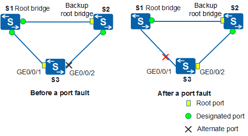
If a root port fails, the best alternate port becomes the root port and enters the Forwarding state. This is because the network segment connected to this alternate port has a designated port connected to the root bridge.
In Figure 2, S1 is the root bridge, S2 is the secondary root bridge, and GE0/0/2 on S3 is the alternate port. If GE0/0/1 on S3 fails:
- In STP mode, GE0/0/2 on S3 switches to the root port and enters the Discarding state. It then waits for an interval of the Forward Delay timer (15s by default) and enters the Learning state, and continues to wait for an interval of the Forward Delay timer and enters the Forwarding state.
- In RSTP mode, GE0/0/2 on S3 switches to the root port and enters the Forwarding state.
Compared with STP, RSTP reduces service traffic loss because the port can directly enter the Forwarding state without waiting for two intervals of the Forward Delay timer.
Edge Port
An edge port is located at the edge of a network and directly connected to a terminal device. This port does not participate in RSTP calculation. An edge port can transition from Disabled state to Forwarding state immediately. It becomes a common STP port once it is connected to a switching device and receives a configuration BPDU. The spanning tree needs to be recalculated, which leads to network flapping.