RSTP Protection Functions
To ensure an RSTP network remains stable, RSTP provides the following protection functions:
- BPDU protection
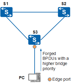
On an RSTP network, an edge port does not receive RST BPDUs in normal situations. If bogus RST BPDUs are sent to a switch enabled with BPDU protection during an attack, the edge port enters the Error-Down state.
In Figure 1, a port on S3 connected to a PC is configured as an edge port. When the edge port receives RST BPDUs, the switch automatically sets the edge port to a non-edge port and performs STP recalculation. If the BID in the RST BPDUs sent by the attacker is higher than the priority of the root bridge, the network topology will change. As a result, service traffic is interrupted. Such an attack is a Denial of Service (DoS) attack.
BPDU protection enables a switch to set the state of an edge port to Error-Down if the edge port receives an RST BPDU. In this case, the port remains as the edge port, and the switch sends a notification to the NMS. The switch generates the following log:
MSTP/4/BPDU_PROTECTION:This edged-port [port-name] that enabled BPDU-Protection will be shutdown, because it received BPDU packet!
- Root protection
The root bridge on a network may receive superior RST BPDUs due to incorrect configurations or malicious attacks. When this occurs, the root bridge can no longer serve as the root bridge and the network topology will incorrectly change. As a result, traffic may be switched from high-speed links to low-speed links, leading to network congestion.
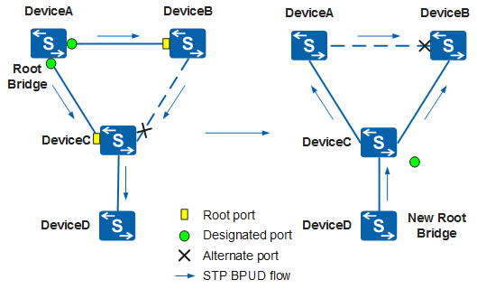
In Figure 2, DeviceA and DeviceB are deployed at the core layer of the network. The bandwidth of the link between these two devices is 1000 Mbit/s. DeviceA is the root bridge on the network. DeviceC is deployed at the access layer. The bandwidth of the links between DeviceC and DeviceA and between DeviceC and DeviceB is 100 Mbit/s. Normally, the link between DeviceB and DeviceC is blocked.
When a new device, DeviceD, is deployed and connects to DeviceC, DeviceD is elected as the new root bridge because it has a higher bridge priority than DeviceA. If the 1000 Mbit/s link between the core switches DeviceA and DeviceB is blocked, VLAN traffic is transmitted through the two 100 Mbit/s links. As a result, network congestion and traffic loss may occur.
In this case, root protection can be configured on DeviceC's port that connects to DeviceD. If root protection is enabled on a designated port, the port role cannot be changed. When the designated port receives a superior RST BPDU, the port enters the Discarding state and does not forward packets. If the port does not receive any superior RST BPDUs within a specified period (two intervals of the Forward Delay timer by default), the port automatically enters the Forwarding state.

Root protection takes effect only on designated ports.
- Loop protection
On an RSTP network, a switching device maintains the states of the root port and blocked ports based on RST BPDUs received from the upstream switching device. If the ports cannot receive RST BPDUs from the upstream switching device because of link congestion or unidirectional link failures, the switching device re-selects a root port. The original root port becomes a designated port, and the original blocked port changes to the forwarding state, which may cause loops on the network.
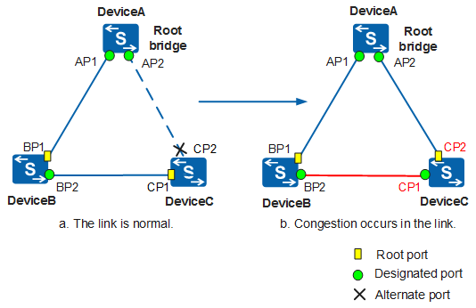
In Figure 3, when the link between BP2 and CP1 is congested, the root port CP1 on DeviceC cannot receive BPDUs from the upstream device. After a specified period, the alternate port CP2 becomes the root port and CP1 becomes the designated port. As a result, a loop occurs.
If the root port or alternate port does not receive BPDUs from the upstream device for a long time, the switch enabled with loop protection sends a notification to the NMS. If the root port is used, the root port enters the Discarding state and becomes the designated port. If the alternate port is used, the alternate port remains blocked and becomes the designated port. In this case, loops will not occur. After the link congestion is cleared or unidirectional link failures are rectified, the port receives BPDUs for negotiation and restores its original role and status.
The switch generates the following log:
MSTP/4/LOOP_GUARD:MSTP process [process-id] Instance[instance-id]'s LOOP-Protection port [port-name] did not receive message in prescriptive time!
Loop protection takes effect only on the root port and alternate ports.
- TC BPDU attack defense
A switching device deletes its MAC address entries and ARP entries after receiving TC BPDUs. If an attacker sends a large number of malicious TC BPDUs to the switching device within a short period, the device will constantly delete MAC address entries and ARP entries. This increases the load on the switching device and threatens network stability.
After enabling TC BPDU attack defense on a switching device, you can set the number of TC BPDUs that the device can process within a specified period. If the number of TC BPDUs that the switching device receives within a given time period exceeds the specified threshold, the switching device processes only the specified number of TC BPDUs. After the time period expires, the switching devices process all the excess TC BPDUs in a batch. In this way, the switch does not need to frequently delete MAC entries and ARP entries.