VLL in Martini Mode
Introduction
VLL in Martini mode uses the Label Distribution Protocol (LDP) as the signaling protocol to transmit VC information. It complies with RFC and extends LDP by adding a forwarding equivalence class (FEC), VC FEC, for VC label switching. A PE device allocates a VC label to each connection between CE devices. VC labels are carried in L2VPN information and forwarded to a remote PE device through an LDP LSP over the public network. As VLL connections are identified using VC labels, multiple VC LSPs can be created on an LSP on the public network. Mappings between VC labels and LSPs are saved only on PE devices, while the P devices do not need to maintain any L2VPN information. Therefore, Martini mode is highly scalable. It also allows multiple VLL connections to use the same public tunnel, which is not supported by the CCC mode.
In Martini mode, a VC is identified by its VC type and VC ID.
VC type: indicates the encapsulation type of a VC, VLAN encapsulation or Ethernet encapsulation.
VC ID: identifies a VC. VCs of the same type must have different VC IDs on a PE device.
Topology
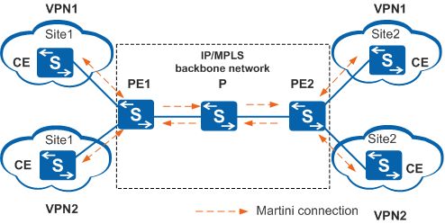
VLL in Martini mode supports only remote connections. Figure 1 shows the topology in Martini mode.
Implementation
Martini implementation involves VLL establishment and VLL packet forwarding. PW establishment is central to VLL establishment. If a PW is established, packets can be forwarded.
The Martini mode uses extended LDP to exchange VC labels. For details about LDP, see VC Information Exchange.
PW Establishment and Teardown
Establishing a PW
The downstream unsolicited (DU) label distribution mode and liberal label retention mode are used to establish a PW. For details, see LDP LSP Establishment in "MPLS LDP Configuration" in the S2720, S5700, and S6700 V200R019C10 Configuration Guide - MPLS.
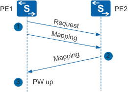
Figure 2 shows the process of establishing a PW using LDP.
PE1 sends a Request packet to PE2 and sends a Label Mapping message to PE2 in DU mode. The Label Mapping message carries information including the VC label, VC type, VC ID, and interface parameters.
After PE2 receives the Request packet, it sends a Label Mapping message to PE1. After PE2 receives the Label Mapping message, it compares VC information carried in the message with its own VC information. If they match, PE1 and PE2 are in the same VLL. PE2 accepts the Label Mapping message, and a unidirectional VC1 is established. PE2 knows the inner VC label to add to packets to send them to PE1.
After PE1 receives the Label Mapping message from PE2, it processes the message in the same way to establish VC2 in the reverse direction. The two unidirectional VCs constitute a PW.
Tearing down a PW
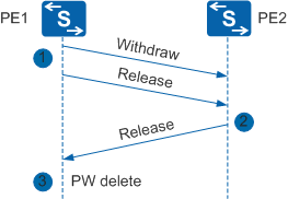
When the AC or tunnel goes Down or a VC is deleted, the PW is torn down. Figure 3 shows the process of tearing down a PW.
When PE1 detects that the AC or tunnel has gone down or a VC has been deleted, it sends a Withdraw message to PE2 to instruct PE2 to delete the VC label. To tear down the PW more quickly, PE1 sends a Withdraw and a Release message consecutively. The Release message notifies PE2 that PE1 has deleted the VC label.
After receiving the Withdraw and Release messages, PE2 deletes the VC1 label and tears down VC1. PE2 then sends a Release message to PE1 to instruct PE1 to delete the VC2 label.
After receiving the Release message, PE1 deletes the VC2 label and tears down VC2. The PW is now torn down.
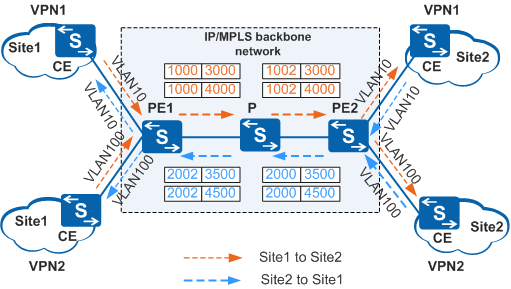
Once a VLL is established, packets can now be forwarded. The following describes the packet forwarding process in Martini mode. Figure 4 shows two VLL networks: VPN1 and VPN2, and packet forwarding in two directions: from Site1 to Site2 and from Site2 to Site1.
From Site1 to Site2
When a packet of VLAN 10 is sent from Site1 of VPN1 to PE1, PE1 adds a VC label 3000 and an outbound label 1000 of LSP1 to the packet. Then the packet enters LSP1 (the orange dashed line). When a packet of VLAN 100 is sent from Site1 of VPN2 to PE1, PE1 adds a VC label 4000 and an outbound label 1000 of LSP1 to the packet. Then the packet enters LSP1 (the orange dashed line).
When packets sent from Site1 reach PE2, PE2 removes the inbound label 1002 of LSP1 and selects the outbound interface based on the inner VC label. If the inner VC label is 3000, PE2 forwards the packet to the outbound interface connected to Site2 of VPN1. If the inner VC label is 4000, PE2 forwards the packet to the outbound interface connected to Site2 of VPN2. PE2 transmits VC labels 3000 and 4000 to PE1 using LDP when they set up the VCs.
From Site2 to Site1
When a packet of VLAN 10 is sent from Site2 of VPN1 to PE2, PE2 adds a VC label 3500 and an outbound label 2000 of LSP2 to the packet. Then the packet enters LSP2 (the blue dashed line). When a packet of VLAN 100 is sent from Site2 of VPN2 to PE2, PE2 adds a VC label 4500 and an outbound label 2000 of LSP2 to the packet. Then the packet enters LSP2 (the blue dashed line).
When packets sent from Site2 reach PE1, PE1 removes the inbound label 2002 of LSP2 and selects the outbound interface according to the inner VC label. If the inner VC label is 3500, PE1 forwards the packet to the outbound interface connected to Site1 of VPN1. If the inner VC label is 4500, PE1 forwards the packet to the outbound interface connected to Site1 of VPN2. PE1 transmits VC labels 3500 and 4500 to PE2 using LDP when they set up the VCs.
In the transmission process, the outer labels specify the LSP for data transmission on the ISP network, and the inner VC labels identify data from different users. Data from multiple VCs can be transmitted over the same LSP.
To deploy VLL in Martini mode, the ISP network must support MPLS forwarding and MPLS LDP.
Martini VLL extends the standard LDP by adding a VC FEC (type 128) to a Label Mapping message to carry VC information during PW establishment.
Figure 5 shows the format of a Label Mapping message. You can see the VC FEC in the Label Mapping message.
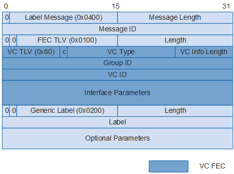
VC FEC contains the inner VC label and interface parameters.
Field |
Description |
Bits |
Remarks |
|---|---|---|---|
VC TLV |
Type, Length, and Value (TLV) of a VC |
8 |
The value is 0x80, or 128 in decimal notation. |
C |
Control word |
1 |
If the value is 1, control word is supported. If the value is 0, control word is not supported. |
VC Type |
Type of a VC |
15 |
The value can be Ethernet or VLAN. |
VC Info Length |
Length of VC information |
8 |
The value is the total length of the VC ID and the Interface Parameters field. |
Group ID |
ID of a VC group |
32 |
Multiple VCs can constitute a VC group and information about all VCs in the group can be deleted together. |
VC ID |
ID of a VC |
32 |
- |
Interface Parameters |
Interface parameters |
Variable, smaller than the value of VC Info Length |
The frequently used interface parameters include MTU and interface description. |