VLL in Kompella Mode
Introduction
Kompella VLL uses the Border Gateway Protocol (BGP) as the signaling protocol to transmit Layer 2 information and VC labels between PE devices.
Similar to BGP/MPLS IP VPN technology, Kompella VLL also uses VPN targets to control advertisement and acceptance of VPN routes, which allows flexible networking. Kompella VLL differs from Martini VLL in inner label distribution. The Kompella mode allocates a label block to each CE device. The label block size determines the number of connections that a local CE device can set up with other CE devices. This label distribution mode can allocate additional labels to VPNs for future capacity expansion. PE devices calculate inner labels based on these label blocks and use the inner labels to transmit packets. To set up a connection between two CE devices, set the local and remote CE IDs on the PE devices connected to the CE devices.
For example, an enterprise VPN has 10 CE devices, and the number may increase to 20 in the future. Here, the CE range (block size) can be set to 20, with 10 labels reserved for new CE devices. When adding CE devices to the VPN, the enterprise only needs to modify the configuration on the PE devices that are directly connected to the new CE devices.
Topology
Kompella VLL supports local and remote connections. Figure 1 shows the topology in Kompella mode.
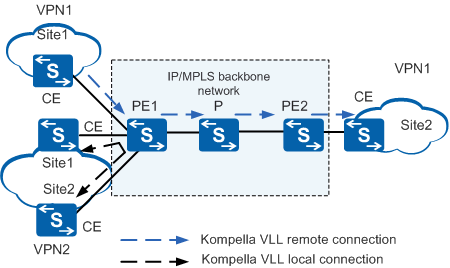
As shown in Figure 1, Site1 and Site2 of VPN1 are interconnected through a Kompella remote connection. Site1 and Site2 of VPN2 are interconnected through a Kompella local connection.
BGP auto-discovery enables the Kompella mode to support more complex topologies.
Implementation
Kompella VLL implementation involves VLL establishment and VLL packet forwarding. PW establishment is central to VLL establishment. If a PW is established, packets can be forwarded.
The PW establishment process requires complex VC label calculation.
The Kompella mode uses extended MP-BGP as the signaling protocol to exchange VC information. For details about the signaling protocol, see VC Information Exchange.
PW Establishment and Teardown
Like the Martini mode, the Kompella mode uses double labels in packet forwarding. The two modes use different signaling protocols to exchange inner label information. The Martini mode uses LDP extensions, whereas the Kompella mode uses MP-BGP. The VC information formats used in the two modes are also different.
MP-BGP carries VC label information in either the MP-reach or MP-unreach attribute. MP-BGP also carries interface parameters, route distinguisher (RD), and VPN targets in the extended community attribute. RD and VPN targets determine VPN membership.
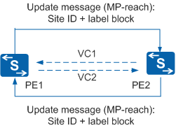
Figure 2 shows the PW establishment process using BGP.
- After a BGP session is established between PE1 and PE2, PE1 sends an Update message with the MP-reach attribute to PE2. The message carries a site ID and label block.
- PE2 calculates a unique label value based on its own site ID and label block information carried in the PE1's Update message. PE2 uses the calculated label value as the VC label to establish a unidirectional VC1, and sends an Update message to PE1. (For details on how the label value is calculated, see VC Label Calculation.) After receiving the Update message, PE1 processes the message in the same way to establish VC2 in the reverse direction.
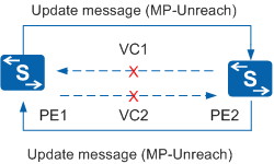
Figure 3 shows the PW teardown process using BGP.
- If PE2 is no longer the peer of PE1, PE1 sends an Update message with the MP-unreach attribute to PE2. After receiving the Update message, PE2 deletes the VC label, tears down VC1, and sends an Update message with the MP-unreach attribute to PE1.
- After receiving the Update message, PE1 deletes the VC label and tears down VC2.
Packet Forwarding
The packet transmission process in Kompella mode is the same as that in Martini mode. For details, see Packet Forwarding in "VLL in Martini Mode."
VC label calculation in Kompella mode is complex.
The Kompella mode uses MP-BGP as the signaling protocol to exchange label blocks. A label block is a range of consecutive labels.
The following values are defined to describe a label block:
Label base (LB): start label in a label block
Label range (LR): size of the label block
Label-block offset (LO)
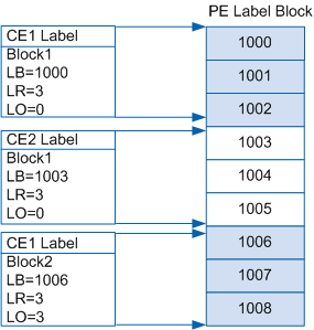
The LO defines the relationship between multiple labels. It identifies the total size of label blocks preceding the current label block on a local CE device.
- As shown in Figure 4, the first label block is CE1's Block1, with the LR of 3 and LO of 0.
- The second label block is CE2's Block1, with the LR of 3 and LO of 0. The LO is 0 because there is no label block for CE2 preceding this block.
- The third label block is CE1's Block2, with the LR of 3 and LO of 3 The LO is 3 because the LR of CE1's Block1 is 3.
The LO is used to calculate VC labels. Each label block can be clearly defined by these parameters: LB, LR, and LO.
When adding the configuration of a CE device on a PE device, you must specify the LR of the label block. The PE device then automatically allocates the LB. This label block is transmitted to other PE devices as a network layer reachable information (NLRI) entry through BGP. When the configuration of this CE device is deleted or the CE device disconnects from the PE device, the PE device deletes the label block and sends a Withdraw message to notify other PE devices.
For example, if CE1 needs to set up two VCs with remote CE devices, the label range for CE1 must be greater than or equal to 2. To allow for future expansion, the label range can be set to 10.
Labels may be insufficient as the number of VCs on the network increases. When this occurs, the label range must be expanded to allow for a larger label space. However, the original label block has been transmitted through the BGP NLRI and used to calculate VC labels and forward data. To protect the original VCs, the CE device can be assigned a new label block, which is then advertised as a new NLRI through BGP. In this way, a CE device can have multiple label blocks, so that the label space can be increased for future network expansion.
CE ID uniquely identifies a CE device in a VPN. Each CE device in a VPN must have a unique CE ID. Each NLRI carries a CE ID so that different label blocks can be associated with corresponding CE devices.
CE IDs can also be used to calculate VC labels, so CE IDs must be set properly. If the CE range configured for a local CE is x and the CE ID of a remote CE is y, x must be larger than y for the connection to work.

If multiple label blocks exist, the range equals the total size of all label blocks.
| Item | Definition | Item | Definition |
| Label block allocated by PE-A to CE-m | Lm | Label block allocated by PE-B to CE-n | Ln |
| Block offset of Lm | LOm | Block offset of Ln | LOn |
| Label base of Lm | LBm | Label base of Ln | LBn |
| Label range of Lm | LRm | Label range of Ln | LRn |
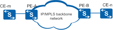
The following describes the VC label calculation process on the network, as shown in Figure 5.
PE-A and PE-B set up a VC for CE-m and CE-n located in the same VPN (m and n are CE IDs).
PE-A receives a label block LBn/LRn/LOn from PE-B.
PE-A checks whether the encapsulation type of CE-n received from PE-B is the same as that of CE-m. If not, PE-A stops the process.
PE-A checks whether the CE IDs m and n are the same. If so, PE-A reports an error and stops the process.
If CE-m has multiple label blocks, PE-A checks whether these label blocks meet the condition of LOm <= n < LOm + LRm. If this condition is not met, PE-A reports an error and stops the process.
PE-A checks whether all the label blocks of CE-n meet the condition of LOn <= m < LOn + LRn. If this condition is not met, PE-A reports an error and stops the process.
PE-A checks whether an outer tunnel has been set up between PE-A and PE-B. If not, PE-A stops the process. In this example, the outer tunnel is an LSP tunnel with the label Z.
PE-A allocates an inner label (LBn + m - LOn) to CE-n (outbound label of the VC), and allocates an inner label (LBm + n - LOm) to CE-m (inbound label of the VC).
The label of the outer tunnel from PE-B to PE-A is Z.
After the inner and outer labels are calculated and the VC is established, Layer 2 packets can be transmitted.
Kompella VLL uses extended MP-BGP NLRI to carry VC information. Similar to L3VPN, Kompella VLL uses RD and VPN targets to identify L2VPN information. It should be noted that VLL technology establishes P2P VCs. To establish VCs from one CE device to multiple CE devices, you must configure multiple interfaces or sub-interfaces. Even if two CE devices are in the same VPN, they can directly communicate only after VCs are established between them.
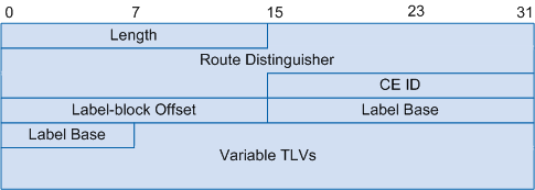
Figure 6 shows the label block in an NLRI. The Variable TLVs contain a Circuit Status Vector (CSV) to specify the LR and tunnel status of the label block.
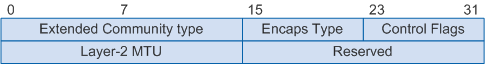
As shown in Figure 7, an extended community attribute is defined to carry more L2VPN information.