VPLS Fundamentals
Basic VPLS Transport Structure
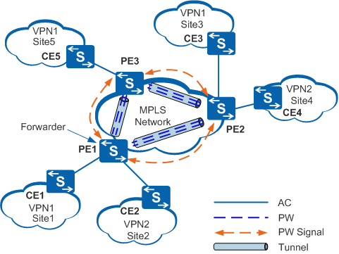
Figure 1 shows an example of a VPLS network. The entire VPLS network functions similarly to a single switch. Pseudowires (PWs) are established over MPLS tunnels between VPN sites to transparently transmit Layer 2 packets. When forwarding packets, provider edges (PEs) learn source MAC addresses of these packets and create MAC entries, mapping MAC addresses to attachment circuits (ACs) and PWs.
The following table describes concepts used in transport on VPLS networks.
Name |
Description |
|---|---|
AC |
A link between a CE and a PE. An AC must be established using Ethernet interfaces. On a VPLS network, AC interfaces can be Ethernet interfaces, VLANIF interfaces, or Eth-Trunk interfaces. |
PW |
A bidirectional virtual connection between two virtual switch instances (VSIs) residing on two PEs. A PW consists of a pair of unidirectional MPLS VCs transmitting in opposite directions. |
Virtual switch instance (VSI) |
A virtual switching unit on the switch for each VPLS. Each VSI has an independent MAC address table and a forwarder. A VSI is responsible for terminating PWs. |
PW signaling |
A type of signaling used to create and maintain PWs. PW signaling is the foundation for VPLS implementation. PW signaling uses Label Distribution Protocol (LDP) or Border Gateway Protocol (BGP). |
Tunnel |
A connection between a local PE and a remote PE used to transparently transmit data between PEs. A tunnel can carry multiple PWs. Tunnel types can be Label Switched Path (LSP) or MPLS Traffic Engineering (MPLS TE). |
Forwarder |
Similar to a VPLS forwarding table. After a PE receives packets from an AC, the forwarder of the PE selects a PW to forward these packets. |
The process of CE1 sending unicast packets to CE3 in VPN1 is as follows:
- PE1, PE2, and PE3 belong to the same VPLS domain. AC links connected to the VPLS domain are mapped to PWs through a VSI to generate the forwarder of the VSI.
- When CE1 receives a Layer 2 packet from a user at Site1, it forwards the Layer 2 packet to PE1 through the AC link.
- After receiving the packet, PE1 discovers that the packet needs to be forwarded in VPLS mode. PE1 then selects a PW from the forwarder to forward the packet based on the destination MAC address of the packet.
- PE1 generates double labels according to the forwarding entry of the PW. The inner private network label identifies the PW, and the outer public network label enables the packet to reach PE2 through the tunnel on the public network. Meanwhile, PE1 searches for the destination MAC address based on the MAC address table index and encapsulates the packet.
- After the Layer 2 packet arrives at PE2 through the tunnel on the public network, the private network label becomes the outer label (the public network label has been popped out at the penultimate hop).
- Once it receives the packet, PE2 selects a VSI for forwarding the packet based on the private network label. PE2 then removes the private network label and selects the forwarder of the VSI. The forwarder forwards the Layer 2 packet to CE3, based on the destination MAC address.
VPLS Implementation Process
Transmission of packets between Customer Edges (CEs) requires on VSIs configured on PEs, and PWs established between the VSIs. Figure 2 shows transmission of Ethernet frames over full-mesh PWs between PEs.
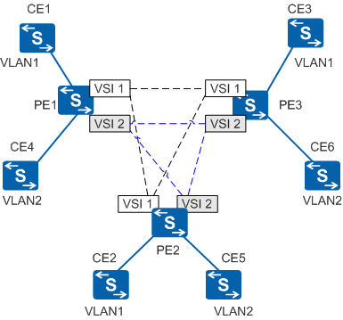
A VPLS network consists of a control plane and a forwarding plane.
The control plane of a VPLS PE provides the PW establishment function, including:
- Member discovery: a process in which a PE in a VSI discovers the other PEs in the same VSI. This process can be implemented manually or automatically using protocols. BGP VPLS and BGP AD VPLS both support automatic member discovery.
- Signaling mechanism: PWs between PEs in the same VSI are established, maintained, or torn down using signaling protocols such as LDP and BGP.
The forwarding plane of a VPLS PE provides the data forwarding function, including:
- Encapsulation: After receiving Ethernet frames from a CE, a PE encapsulates the frames into packets and sends the packets to VPLS network.
- Forwarding: A PE determines how to forward a packet based on the inbound interface and destination Media Access Control (MAC) address of the packet.
- Decapsulation: After receiving packets from VPLS network, a PE decapsulates these packets into Ethernet frames and sends the frames to a CE.