PW Signaling Protocols
PW Signaling Protocols and VPLS Implementation Modes
Table 1 compares these VPLS implementation modes.
Implementation Mode |
Description |
Usage Scenario |
|---|---|---|
LDP mode (also called Martini) |
|
Typically used on VPLS networks that have few sites, do not span multiple ASs, and with PEs that cannot run BGP. |
BGP mode (also called Kompella) |
|
Typically used on VPLS networks that reside on the core layers of large-scale networks or span multiple ASs. PEs must be able to run BGP. |
BGP AD mode |
The BGP AD mode uses extended BGP Update packets to implement automatic member discovery. It also supports VPLS PW establishment.
|
BGP AD mode integrates the advantages of the BGP and LDP modes. |
LDP VPLS
Introduction to LDP VPLS
LDP VPLS (Martini VPLS) statically discovers VPLS members using LDP signaling. VPLS information is carried in extended TLV fields (type 128 and type 129 FEC TLVs) of LDP signaling packets. During the establishment of a PW, the label distribution mode is downstream unsolicited (DU) and the label retention mode is liberal.
Implementation process
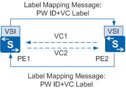
Figure 1 shows the process of establishing a PW using LDP signaling.
- After PE1 is associated with a VSI, and PE2 is configured as a peer of PE1, PE1 sends a Label Mapping message to PE2 in DU mode if an LDP session already exists between PE1 and PE2. The Label Mapping message carries information required to establish a PW, such as the PW ID, VC label, and interface parameters.
- After receiving the message, PE2 checks whether it has been associated with the VSI. If PE2 has been associated with the VSI and the PW parameters on PE1 and PE2 are the same, PE1 and PE2 belong to the same VSI. In this case, PE2 establishes a unidirectional VC named VC1 immediately after PE2 receives the Label Mapping message. Meanwhile, PE2 sends a Label Mapping message to PE1. After receiving the message, PE1 takes a similar sequence of actions to PE2 to establish VC2.
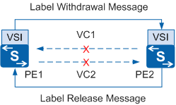
Figure 2 shows the process of tearing down a PW using LDP signaling.
- After the peer configuration of PE2 is deleted from PE1, PE1 sends a Label Withdrawal message to PE2. After receiving the Label Withdrawal message, PE2 withdraws its local VC label, tears down VC1, and sends a Label Release message to PE1.
- After receiving the Label Release message, PE1 withdraws its local VC label and tears down VC2.
BGP VPLS
Introduction to BGP VPLS
BGP VPLS (Kompella VPLS) dynamically discovers VPLS members using BGP signaling. BGP VPLS uses MP-BGP packets to transmit VPLS member information. The MP-REACH and MP-UNREACH attributes carry VPLS label information; the extended community attributes carry interface parameters, RDs, and VPN targets; the RDs and VPN targets identify VPN member relationships.
Implementation process
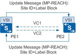
Figure 3 shows the process of establishing a PW using BGP signaling.
In order to establish a PW using BGP signaling, a BGP session must already exist between PE1 and PE2. The process is as follows:
- After PE1 is associated with a VSI and PE2 is configured as PE1's peer, PE1 sends an Update packet carrying the MP-REACH attribute, site ID, and label block information to PE2.
- Upon receipt, PE2 calculates a unique label as the VC label based on its own site ID and label block. PE2 then establishes a unidirectional VC VC1. Meanwhile, PE2 calculates the VC label of PE1 based on the site ID and label block carried in the Update packet sent by PE1. Using this information, PE2 sends an Update packet to PE1. After receiving the Update packet, PE1 takes similar actions to PE2 to establish VC2.
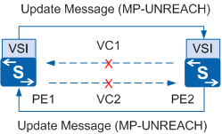
Figure 4 shows the process of tearing down a PW using BGP signaling.
- After the peer configuration for PE2 is deleted from PE1, PE1 sends an Update packet carrying the MP-UNREACH attribute to PE2. After receiving the packet, PE2 withdraws its local VC label, tears down VC1, and sends an Update packet carrying the MP-UNREACH attribute to PE1.
- After receiving the Update packet, PE1 withdraws its local VC label and tears down VC2.
BGP AD VPLS
Introduction to BGP AD VPLS
BGP AD VPLS, short for Border Gateway Protocol Auto-Discovery Virtual Private Line Service, is a new technology for automatically deploying VPLS services.
BGP AD VPLS-enabled devices exchange extended BGP Update packets to automatically discover BGP peers in a VPLS domain. After BGP peer relationships are established, these devices use LDP FEC 129 to negotiate and establish VPLS PWs. In addition, BGP AD Hierarchical Virtual Private LAN Service (HVPLS) is deployed by disabling split horizon. This allows all BGP peers in an AS to function as user-end provider edges (UPEs) on an HVPLS network.
Purpose
As VPLS technology becomes more widely used, VPLS networks grow in size and complexity. BGP AD VPLS is used to simplify configurations using automatic VPLS member discovery and automatic PW deployment. This allows services to be deployed automatically and reduces OPEX.
BGP AD VPLS has the advantages of both LDP and BGP VPLS. BGP AD VPLS-enabled devices exchange extended BGP Update packets to automatically discover BGP peers in a VPLS domain. After BGP peer relationships between them are established, the devices use LDP FEC 129 to negotiate and establish VPLS PWs. VPLS services are automatically deployed on these PWs.
Related Concepts
Acronym and Abbreviation |
Full Name |
Description |
|---|---|---|
VPLS ID |
Virtual Private LAN Service ID |
Identifier of a VPLS domain |
AGI |
Attachment Group Identifier |
Domain identifier used during PW negotiation between PEs in a VPLS domain |
AII |
Attachment Individual Identifier |
VSI identifier used during PW negotiation between PEs in a VPLS domain |
SAII |
Source Attachment Individual Identifier |
Local IP address used by BGP AD VPLS to negotiate the creation of a PW |
TAII |
Target Attachment Individual Identifier |
Remote IP address used during negotiation on the creation of a PW |
FEC 129 |
Forwarding Equivalence Class 129 |
New type of FEC used by LDP signaling |
Implementation
BGP AD VPLS automatically discovers VPLS BGP peers, simplifying configuration and saving labels.
BGP AD VPLS-enabled devices exchange extended BGP Update packets carrying VSI information and automatically discover BGP peers in a VPLS domain. After BGP peer relationships are established, these devices use LDP FEC 129 to negotiate and establish VPLS PWs. VPLS services are automatically deployed on these PWs.
Automatically Discovering PEs in a VPLS Domain
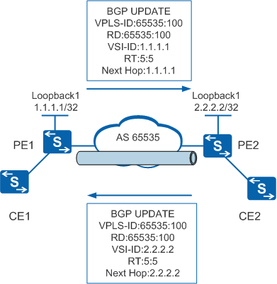
Automatically discovering PEs in a VPLS domain is the first phase of VPLS service deployment. BGP is used to automatically discover PEs in a VPLS domain. Figure 5 shows the process of and information used for automatically discovering PEs in a VPLS domain.
The process of automatically discovering PEs in a VPLS domain is as follows:
- The VPLS ID, RT, VSI ID are set on PE1 and encapsulated in BGP AD Update messages. These messages are sent to all peer PEs in all BGP areas. The operations and process are the same on PE2.
 By default, the RD is equal to the VPLS ID. If the VPLS ID is set, the RD does not need to be set. The VSI ID is equal to the local LSR ID and does not need to be set.
 - After receiving BGP AD packets, PEs check whether the BGP AD packets match the RT policy. If they match, PEs obtain the VSI information carried in the packets and compare the obtained information to the local configuration. After comparison, one of the following results is obtained:
- If VPLS IDs of VSIs on both PEs are the same, the two VSIs are in the same VPLS domain. Only one PW can be established between them.
- If VPLS IDs of VSIs on two PEs are different, the two VSIs are in different VPLS domains. A PW cannot be established between them.
- The VPLS ID, RT, VSI ID are set on PE1 and encapsulated in BGP AD Update messages. These messages are sent to all peer PEs in all BGP areas. The operations and process are the same on PE2.
Automatically Deploying a PW
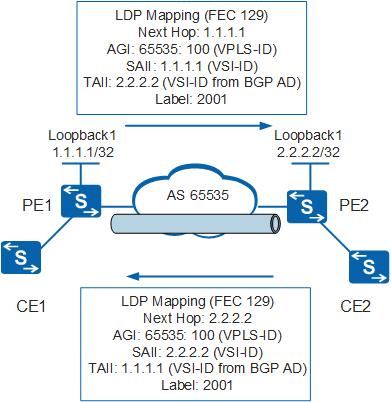
After a PE discovers remote PEs in a VPLS domain, BGP AD uses LDP FEC 129 to negotiate the creation of PWs. Figure 6 shows the negotiation process.
The process of automatically deploying a PW is as follows:
- If no LDP session exists between two PEs in the same VPLS domain, the two PEs still initiate negotiation to establish an LDP session. Once an LDP session is already established, the PEs exchange LDP Mapping messages by using FEC 123 signaling. The LDP Mapping messages carry information such as AGI, SAII, TAII, and the label. After BGP AD VPLS members are discovered, BGP AD VPLS actively triggers LDP to establish an LDP session, allowing the establishment of a PW for VPLS services. If VPLS services are deleted and the LDP session is no longer used, LDP deletes the LDP session. This simplifies maintenance, increases the efficiency of network and system resource use, and improves network performance.
- After a PE receives an LDP Mapping message, the PE parses and obtains information including the VPLS ID, PW type, MTU, and TAII. The PE compares this information to the local VSI information. If the information is the same and meets the requirements for establishing a PW, the PEs establish a PW.
- If no LDP session exists between two PEs in the same VPLS domain, the two PEs still initiate negotiation to establish an LDP session. Once an LDP session is already established, the PEs exchange LDP Mapping messages by using FEC 123 signaling. The LDP Mapping messages carry information such as AGI, SAII, TAII, and the label.