VPLS Convergence
Introduction
VPLS convergence is a solution for transmitting data from the convergence layer to the access layer in a Metro Ethernet network. VPLS convergence involves dual homing an underlayer provider edge (UPE) to superstratum provider edges (SPEs), ensuring high reliability.
When VPLS convergence is used, HVPLS connections or VPLS connections are established between the UPE and SPEs (or PE-AGGs), and management Virtual Router Redundancy Protocol (mVRRP) runs between SPEs to determine master/backup status. The master/backup status of a PW interface or an AC interface between VSIs is determined by tracking the mVRRP status.
When mVRRP performs a master/backup switchover, PW interfaces or AC interfaces between VSIs also perform a master/backup switchover. At the same time, the VSI clears its MAC address and learns the MAC address of the new master device.
If VPLS convergence is used, the switch can be used as a UPE and have an mVSI configured.
Benefits
VPLS convergence has many advantages, including low cost, wide applications, good compatibility with multicast, easy expansion, and high security.
mVPLS
mVPLS refers to management VPLS. VSIs using mVPLS are called mVSIs.
The conditions for entering the Up state for mVSIs are mostly the same as those for normal VSIs (service VSIs). The difference is as follows:
Service VSI: requires two or more Up AC interfaces, or an Up AC interface and an Up PW.
mVSI: requires only an Up PW or an Up AC interface.
The mVSI can be bound with the service VSI. Once bound, if the mVSI receives gratuitous ARP packets, it instructs all the bound service VSIs to clear the MAC address entries and relearn the MAC address.
mVRRP
mVRRP refers to management VRRP. An mVRRP backup group is a type of VRRP backup group. An mVRRP backup group can be bound to service VRRP backup groups. Once bound, the mVRRP backup group determines the status of service VRRP backup groups according to the binding relationship.
An mVRRP backup group can be bound to multiple service VRRP backup groups but cannot be bound to other mVRRP backup groups.
mVRRP over mVPLS
In mVRRP over mVPLS, mVRRP packets are exchanged by the mVSI and transmitted through the mPW.
In Figure 1, mVPLS is run between the UPE and the SPEs. An mVSI is configured on the UPE and the SPEs; mVRRP is run between SPEs. mVRRP packets are transmitted through the mPW between the UPE and the SPEs and forwarded by the mVSI. Other service packets are transmitted through the service PW and exchanged by the service VSI between the UPE and the SPEs.
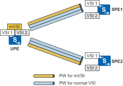
mVRRP packets and other service packets are transmitted through different PWs, so that they are separated from each other. To enable the fast switchover of mVRRP backup group between the SPEs, you need to configure peer BFD between SPEs. Peer BFD packets are also transmitted through the mPW and exchanged by the mVSI.
The mVSI and the service VSI are bound on the UPE. When the VRRP backup group on the SPE performs master/backup switchover, the following occurs:
The mVSI on the UPE receives the gratuitous ARP packet sent from the SPE through the mPW between the UPE and the SPEs.
The mVSI checks whether the received gratuitous ARP packet is the same as the one previously received. To do this, the mVSI checks whether both packets are received through the same PW and whether their IP addresses, incoming labels, incoming interfaces, and MAC addresses are the same.
If they are the same, the mVRRP backup group between SPEs has not performed a master/backup switchover.
If they are the different, the mVRRP backup group between SPEs has performed a master/backup switchover.
The UPE clears the MAC addresses of all bound service VSIs according to the binding of the mVSI and the service VSI. The service VSI on the UPE sends mac-withdraw messages to all peer devices of the VSI. After receiving mac-withdraw messages, the remote peers clear the MAC addresses on the PW side.
When the service VSI receives a packet destined for the new SPE after the MAC address of the original master SPE is cleared, the service VSI broadcasts the packet. It does so because the packet is encapsulated in an unknown frame. After receiving the packet, the master SPE learns the source MAC address of the packet for reverse traffic forwarding.
Unlike service VSIs, the mVSI is used to transmit and intercept the ARP and BFD packets. Users are therefore not allowed to shut down the mVSI.
Determining the Master and Backup Using mVRR in Dual-Homing Networking
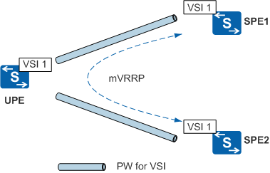
In Figure 2, the underlayer provider edge (UPE) is dual-homed to the network provider edges (SPEs). VRRP is run between SPEs. The VRRP priority determines whether an SPE is the master or the backup. When the link related to the master SPE fails or the master SPE itself fails, the backup SPE can switch itself to be the master SPE.
To satisfy the requirements of different services, multiple VRRP backup groups can be run between SPEs. Each VRRP backup group needs to maintain its own state machine; therefore, a large number of VRRP protocol packets exist between SPEs. To simplify the operation and reduce the bandwidth occupied by protocol packets, you can configure one VRRP backup group to be an mVRRP backup group and bind it to other service backup groups. Then the status of the service backup group is determined by the status of the bound mVRRP backup group.
In different application scenarios, the bindings of mVRRP fall into the following types:
Binding of the service backup group and the mVRRP backup group
After the service backup group is bound to the mVRRP backup group, the state machine of the service backup group becomes dependent. The service backup group deletes the protocol timer, no longer sends or receives protocol packets, and implements its state machine by directly copying the status of the mVRRP backup group. The service backup group can be bound to only one mVRRP backup group. The mVRRP backup group is identified by the backup group ID (VRID) and the interface configured with the backup group.
Binding of the service interface (also regarded as the member interface) and the mVRRP backup group
In Figure 2, if the UPE is dual-homed to the SPEs through two physical links, you can bind the service interface and the mVRRP backup group to determine whether a service interface is the master or the backup.
When the status of the mVRRP backup group bound to the service interface changes to Master, the mVRRP backup group notifies all the bound service interfaces of the change.
If L3 services are run on the interface, the status of the interface is set to Up and the network segment route is generated. The forwarding plane enables the bidirectional traffic forwarding according to the interface status. If L2 services are run on the interface, the status of the interface is directly set to Up, and the forwarding plane enables the bidirectional traffic forwarding.
When the status of the mVRRP backup group bound with the service interface changes to Initialize or Backup, the mVRRP backup group notifies the change to all the bound service interfaces.
If L3 services are run on the interface, the status of the interface is set to Down and the network segment route is deleted. The forwarding plane disables the bidirectional traffic forwarding. If L2 services are run on the interface, the status of the interface is directly set to Down. The forwarding plane disables the bidirectional traffic forwarding.
Binding of the PW and the mVRRP backup group
In Figure 2, if Virtual Leased Line (VLL), Pseudo-Wire Emulation Edge to Edge (PWE3), or VPLS is run between the UPE and the SPEs, the UPE is dual-homed to the SPEs. You can bind the PW and the mVRRP backup group to determine whether a PW is the master or the backup.
If the original status of the PW is Down, the PW status remains Down.
If the original status of the PW is Up, the PW status remains Up if the mVRRP backup group is in the Master state. The PW status becomes Down if the mVRRP backup group is in the Backup state.
The two SPEs can share the load, as shown in Figure 3.
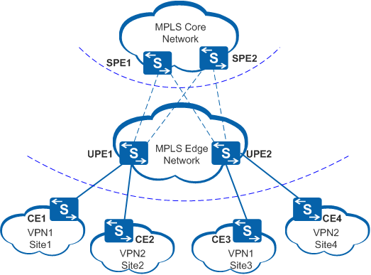
Multiple mVRRP backup groups are run between the SPEs. The services choose different SPEs as the master SPE through bindings with different mVRRP backup groups. For example, a user of UPE1 uses SPE1 as the master SPE and uses SPE2 as the backup SPE. A user of UPE2 uses SPE2 as the master SPE and uses SPE1 as the backup SPE.
Influencing the State Machine of a VRRP Virtual Router Using Link BFD and Peer BFD
In Figure 4, VRRP is run between the SPE1 and SPE2. BFD running between the two SPEs is called peer BFD. BFD running between the UPE and the SPEs is called link BFD. Peer BFD is used to detect faults with devices and links between SPEs. Link BFD is used to detect faults with devices and links between the UPE and the SPEs.
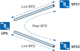
The status of peer BFD and link BFD sessions and the status of the normal BFD for VRRP session have different impacts on the VRRP backup group: The status of the peer BFD session and the link BFD session directly affects the status of the VRRP backup group. The status of the ordinary BFD for VRRP session indirectly affects the status of the VRRP backup group by modifying the priority. Modifying priority, however, does not necessarily change the status of the VRRP backup group.
mVRRP can implement master/backup switchover more rapidly and locate faults by tracking peer BFD status and link BFD status.