Interworking Between LDP VPLS and BGP AD VPLS
Background
LDP VPLS uses LDP signaling packets that carry FEC 128 TLV fields to establish and maintain PWs. Its requirements for device performance are quite low, because peers are manually specified for PW establishment. BGP AD VPLS uses BGP to automatically discover VPLS members and uses LDP signaling packets that carry FEC 129 TLV fields to establish and maintain PWs. PWs are automatically established by BGP AD VPLS. Requirements for device performance are therefore high.
LDP VPLS is typically used on VPLS networks with a small number of sites, whereas BGP AD VPLS is typically used on VPLS networks with a large number of sites. As networks develop, service providers increasingly require communication between LDP and BGP AD VPLS networks. Interworking between LDP VPLS and BGP AD VPLS was developed to meet this demand, allowing for seamless interconnection between LDP and BGP AD VPLS networks.
Implementation
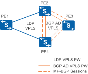
To enable an LDP VPLS network to communicate with a BGP AD VPLS network, edge nodes between the two networks must support both LDP VPLS and BGP AD VPLS. In Figure 1, PE1 supports LDP VPLS, PE3 supports BGP AD VPLS, and PE2 and PE4 support both LDP VPLS and BGP AD VPLS. PE1, PE2, and PE4 form an LDP VPLS network, and PE3, PE2, and PE4 form a BGP AD VPLS network. On PE2 and PE4, the signaling negotiation for LDP VPLS is independent of that for BGP AD VPLS. For the establishment and maintenance of an LDP VPLS PW, see LDP VPLS. For details about member discovery and PW establishment, see BGP AD VPLS. After PWs are established, PEs can exchange data packets over these PWs. Data packet encapsulation on an LDP VPLS network is similar to that on a BGP AD VPLS network. For details, see Packet Encapsulation.
Derivative Function (MAC Withdraw)
On LDP, BGP AD, or LDP + BGP AD VPLS networks, when link failures, device failures, or active/standby switchovers occur, the PE sends a MAC Withdraw message to remote peers. Upon receipt, the remote peers remove MAC entries in their VSIs based on the MAC Withdraw message. LDP VPLS network supports only MAC Withdraw messages that carry the FEC 128 TLV field, whereas BGP AD VPLS network supports only MAC Withdraw messages that carry the FEC 129 TLV field. To support MAC Withdraw, LDP + BGP AD VPLS network must be able to convert between these two types of MAC Withdraw messages.
In Figure 2, the PW from PE4 to PE1 is the primary PW and the PW from PE4 to PE2 is the secondary PW. The link from CE1 to PE1 is the primary link and the link from CE1 to PE3 is the secondary link.
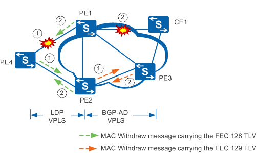
If the PW from PE4 to PE1 fails, the following occurs:
- PE4 performs a primary/secondary PW switchover and sends a MAC Withdraw message carrying the FEC 128 TLV field to PE2.
- PE2 receives the message and removes MAC entries in its VSI based on the MAC Withdraw message. PE2 converts the message to a MAC Withdraw message carrying the FEC 129 TLV field and forwards the new MAC Withdraw message to PE3.
- After receiving the MAC Withdraw message, PE3 removes MAC addresses in its VSI based on the MAC Withdraw message.
- When the PW from PE4 to PE1 recovers, PE4 performs a revertive switchover based on the configured revertive switching policy. PE4 sends a MAC Withdraw message carrying the FEC 128 TLV field to PE1.
- PE1 receives the message and removes MAC entries in its VSI based on the MAC Withdraw message. PE1 converts the message to a MAC Withdraw message carrying the FEC 129 TLV field, and forwards the new MAC Withdraw message to PE3.
- After receiving the message, PE3 removes MAC addresses in its VSI based on the MAC Withdraw message.
If the AC from CE1 to PE1 fails, the following occurs:
- PE1 sends a MAC Withdraw message carrying the FEC 128 TLV field to PE4 after PE1 detects the status change of its AC interface. PE3 sends a MAC Withdraw message carrying the FEC 129 TLV field to PE2 after detecting the AC status change.
- After PE2 receives the MAC Withdraw message sent from PE3, PE2 removes the MAC entries in its VSI based on the MAC Withdraw message. PE2 then converts the message to a MAC Withdraw message carrying the FEC 128 TLV field, and forwards the new MAC Withdraw message to PE4.
- After PE4 receives the MAC Withdraw messages sent from PE1 and PE2, PE4 removes the MAC addresses in its VSI based on the messages.
- When the AC from CE1 to PE1 recovers, PE1 sends a MAC Withdraw message carrying the FEC 128 TLV field to PE4 after detecting the AC status change.
- PE3 sends a MAC Withdraw message carrying the FEC 129 TLV field to PE2 after detecting the AC status change.
- After PE2 receives the MAC Withdraw message sent from PE3, PE2 removes the MAC entries in its VSI based on the MAC Withdraw message. PE2 then converts the message to a MAC Withdraw message carrying the FEC 128 TLV field and forwards the new MAC Withdraw message to PE4.
- After PE4 receives the MAC Withdraw messages sent from PE1 and PE2, PE4 removes the MAC addresses in its VSI based on the messages.