Bluetooth Terminal Location
Concepts
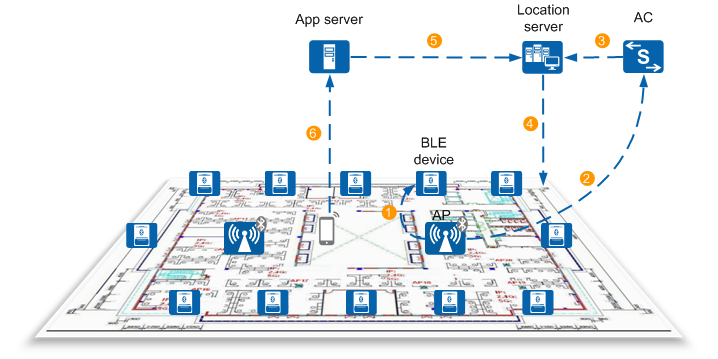
BLE device: is a Bluetooth signal generator that periodically sends BLE broadcast frames to surrounding devices. The frame content complies with the iBeacon protocol.
- AP: scans BLE broadcast frames sent by BLE devices, obtains BLE device information such as UUIDs, RSSI calibration values, and power, reports the information to an AC, and sends Bluetooth terminal location packets to an AC or a server.
- AC: delivers the Bluetooth location function configuration. It also sends Bluetooth terminal location packets, and lower power and fault alarm information to a location server.
- Location server: allows BLE base stations to be set and location maps to be made, calculates Bluetooth terminal locations, and monitors the status of BLE base stations.
- App server: obtains map information and BLE device locations from the location server, and sends the information to Bluetooth terminals.
- Bluetooth terminal: periodically sends iBeacon broadcast frames, receives signal strength of BLE base stations and sensor data, and works with the mobile app to calculate Bluetooth terminal locations using location algorithms.
Implementation
An AP obtains information about BLE devices and Bluetooth terminals, such as UUIDs, RSSI calibration values, and power.
The AP's built-in Bluetooth module scans surrounding BLE devices and Bluetooth terminals, and collects iBeacon broadcast frames sent by them. The iBeacon broadcast frames carry device information such as UUIDs and RSSI calibration values.
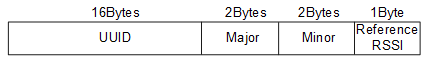
BLE devices and Bluetooth terminals periodically send iBeacon broadcast frames without the need to access the WLAN. Figure 2 shows the format of an iBeacon broadcast frame.Fields of an iBeacon broadcast frame are described as follows:- UUID: universally unique identifier for identifying BLE devices or Bluetooth terminals
- Major: field customized by device vendors for identifying a major group
- Minor: field customized by device vendors for identifying a minor group
- Reference RSSI: RSSI calibration value measured 1 meter away from a BLE device or Bluetooth terminal
- The AP sends power query requests to surrounding BLE devices or Bluetooth terminals. After receiving the requests, the BLE devices or Bluetooth terminals send scan response broadcast frames carrying power information on broadcast channels. Figure 3 describes the format of a scan response broadcast frame.
Fields of a scan response broadcast frame are described as follows:
- Data Length: length of the first part of data, including the length of Local name and Data
- Local name: iBeacon protocol data format, indicating that the subsequent data is a device name
- Data: device name customized by device vendors
- Data Length: length of the last part of data, including the length of the Service Data, Service UUID, and Battery volume fields
- Service Data: iBeacon protocol data format, indicating that the subsequent data is a UUID
- Service UUID: universally unique identifier customized by device vendors for identifying BLE devices or Bluetooth terminals
- Battery volume: battery power level ranging from 0 to 100 in decimal notation that maps battery power from 0% to 100%.
The AP reports obtained information about BLE devices, such as UUIDs, RSSI calibration values, and power, to the AC, and sends Bluetooth terminal location packets to the AC or location server.
In scenarios where no independent BLE devices are deployed, the Bluetooth broadcast function of APs' built-in Bluetooth modules can be enabled, so that APs can function as BLE devices to send BLE broadcast frames. Then APs can directly report battery power, UUIDs, and RSSI calibration values of built-in Bluetooth modules to an AC without the need of scanning.
- The AC sends Bluetooth terminal location packets, and lower power and fault alarm information about BLE devices to the location server.
- On the location server, make floor plans and location map models, add BLE devices, set their deployment locations, monitor their status, and calculate Bluetooth terminal locations.
- The app server obtains map information and BLE locations from the location server.
- The app server sends map information and BLE device locations to Bluetooth locations.
- Install a location app on a Bluetooth terminal (such as a mobile phone), start the app, and perform the following operations:
- Collect information about scanned BLE devices and their signal strengths.
- Collect information about sensors of the mobile phone, such as speed sensors and Gyroscopes.
- Obtain map information from the location server.
- Calculate and display BLE device locations on the Bluetooth terminal.