Implementation of Vehicle-Ground Fast Link Handover
Implementation of vehicle-ground fast link handover includes Mesh link setup and teardown, fast link handover, and multicast data guarantee.
Mesh Link Setup and Teardown
To enable vehicle-ground communications, a vehicle-mounted AP sets up Mesh links with neighboring trackside APs. If the Received Signal Strength Indicator (RSSI) of a trackside AP is greater than or equal to N (N = Minimum RSSI threshold of a Mesh link - 5 dB) and the number of Mesh links has not reached the maximum, the vehicle-mounted AP sets up a Mesh link with the trackside AP according to the common Mesh link setup process. For details, see Principle Description-Mesh Implementation in "Mesh Configuration."
The vehicle-mounted AP sets up Mesh links with multiple trackside APs and chooses one qualified Mesh link as the active link to transmit data. Other links act as candidate links. As the train moves forward, the vehicle-mounted AP chooses the candidate link of the best quality as the active link to implement fast handover so that quality of vehicle-ground communications is always at the optimal level.
If the RSSI of a Mesh link is smaller than N (N = Minimum RSSI threshold of a Mesh link - 5 dB) and the Mesh link is not the active link, the vehicle-mounted AP tears down the link so that it can set up a better Mesh link with another trackside AP.
Vehicle-Ground Fast Link Handover
A vehicle-mounted AP chooses the active Mesh link using the basic or location-based vehicle-ground fast link handover algorithm. The two algorithms determine whether to perform a common handover or an emergency handover based on link conditions.
Basic handover algorithm
- Common handover: As a train moves forward, a common link handover is triggered if the RSSI of a candidate link meets the following conditions:
- The RSSI difference between the candidate link and current active link is greater than or equal to the RSSI threshold for a Mesh link handover.
- The candidate link belongs to the candidate area.

The RSSI range of a candidate area is from the minimum RSSI threshold to the maximum RSSI threshold of the Mesh link. Candidate links with RSSI values in this range belong to the candidate area.
- The serving time of the current active link is longer than or equal to the link holding time.
A holding time is specified for the active link to prevent frequent handovers. The serving time of the active link must be longer than or equal to the specified holding time; otherwise, the vehicle-mounted AP can only implement an emergency handover, not a common handover.
If multiple candidate links meet common handover conditions, the candidate link with the highest RSSI is chosen as the active link.
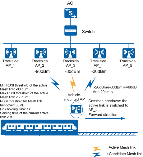
In Figure 1, the RSSI of AP_4 (in the candidate area) is -20 dBm. The RSSI difference between AP_4 (-20 dBm) and the active link (-80 dBm) is 60 dB, equal to the RSSI threshold for a Mesh link handover. In addition, the serving time of the current active link (20s) is longer than the link holding time (1s). All conditions for a common handover are met; therefore, the vehicle-mounted AP switches the active link to AP_4.
An emergency handover occurs in the following situations.
- The RSSIs of candidate links have not satisfied the common handover conditions but the RSSI of the current active link is out of the RSSI range of the candidate area (falls below the minimum RSSI threshold of a Mesh link or exceeds the maximum RSSI threshold of a Mesh link).
- The RSSI of the current active link is still within the allowed range, but the link rate has fallen below the minimum rate threshold or stayed in this low-speed state longer than the minimum rate holding time.
When performing an emergency handover, the vehicle-mounted AP chooses the candidate link with the highest RSSI as the active link from the candidate area. If no candidate link meets the requirement and the current active link is still connected, the AP retains the current active link and does not perform an emergency handover.
If the current active link is disconnected due to a trackside AP fault or when the train leaves the originating station, no active link is available. The vehicle-mounted AP then performs an emergency handover. The vehicle-mounted AP selects the candidate link of the best quality as the active link from the candidate area. If no candidate link in the candidate area meets the requirement, the vehicle-mounted AP selects the candidate link with the highest RSSI in another area as the active link.
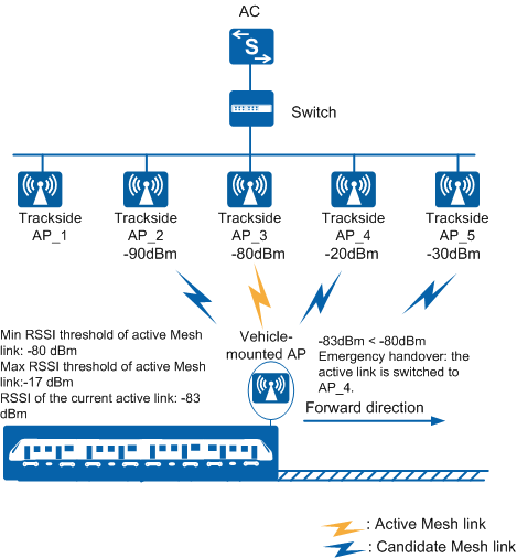
In Figure 2, the RSSI of trackside AP_3 decreases to -83 dBm, which is smaller than the minimum RSSI threshold (-80 dBm) of a Mesh link. An emergency handover is triggered, and the vehicle-mounted AP switches the active link to AP_4 with the highest RSSI in the candidate area.
If the RSSIs of AP_4 and AP_5 are -12 dBm and -15 dBm respectively, out of the range from -80 dBm to -17 dBm, no candidate link qualifies as an active Mesh link. In this case, the vehicle-mounted AP retains its connection with AP_3. If AP_3 becomes faulty, the current active link is disconnected. The vehicle-mounted AP then switches the active link to AP_4 (-12 dBm).
An emergency handover may occur when the radio environment is unstable or a trackside AP fails. To prevent back and forth handovers between trackside APs (ping-pong handovers), you can configure penalty parameters for an emergency handover. The penalty parameters include the penalty period and penalty level. When an emergency handover occurs, the vehicle-mounted AP disconnects the active link from a trackside AP. If the RSSI of the trackside AP falls within the RSSI range of the candidate area before the penalty period expires, the vehicle-mounted AP deducts the penalty level from the RSSI of the trackside AP before comparing it with the RSSIs of other links.
Location-based enhanced handover algorithm
The location-based enhanced handover algorithm incorporates location information of trackside APs into the basic handover algorithm to determine whether to perform a common or emergency handover.
In vehicle-ground communication scenarios, signals of a trackside AP distant from a train may be temporarily better than the trackside AP near the train due to radio environment changes. If an active link handover occurs at this time, the active link may be incorrectly switched to the distant trackside AP. To prevent incorrect handovers and improve vehicle-ground communication quality, you can use the location-based enhanced link handover algorithm. This algorithm requires that trackside APs be named in ascending or descending order of sequence numbers.
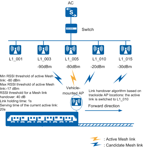
Trackside APs should be named in head-name_sequence-number format. head-name describes track line information and can be different for trackside APs on the same track. It is recommended that you set the same head-name for APs on a track to differentiate tracks. sequence-number of APs along a track must be in descending or ascending order. The sequence numbers of trackside APs can be set with unequal steps. head-name and sequence-number are separated using an underscore (_), for example, L1_001, L1_002, L1_005, L1_010.
The location-based enhanced link handover algorithm gives priority to trackside APs that are near the train and meet handover requirements. In Figure 3, the vehicle-mounted AP detects that the RSSIs of L1_003, L1_010, and L1_015 are -20 dBm, -40 dBm, and -30 dBm respectively. All trackside APs meet RSSI requirements for a common handover. According to the basic link handover algorithm, the vehicle-mounted AP will switch the active link to L1_003 with the highest RSSI. If the location-based enhanced link handover algorithm is used, the vehicle-mounted AP will switch the active link to the nearest trackside AP L1_010.
Multicast Data Guarantee
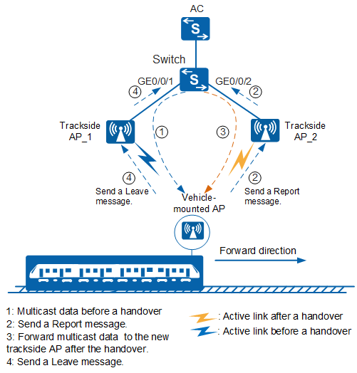
Vehicle-mounted multimedia devices on moving trains deliver multimedia information services to passengers in multicast mode. Reliable multicast data transmission ensures smooth delivery of multimedia information services. All vehicle-mounted multimedia devices are added to a multicast group. As the train moves ahead, the active link changes frequently. Only the trackside AP and vehicle-mounted AP are aware of the link change. Other ground devices such as switches connected to trackside APs cannot detect the change and fail to forward multicast data. To resolve the problem, IGMP snooping is enabled on the vehicle-mounted AP and ground devices to generate Layer 2 multicast forwarding entries. After switching the active link to a new trackside AP, the vehicle-mounted AP sends a Report message to the trackside AP. The trackside AP forwards the message to the ground device, which then updates the multicast forwarding table accordingly. To prevent loss of multicast packets during a link handover, the vehicle-mounted AP still receives multicast data from the old trackside AP before the multicast flow is switched to the new trackside AP. After receiving multicast data from the new trackside AP, the vehicle-mounted AP sends a Leave message to the old trackside AP. The old trackside AP forwards the Leave message to the ground device, which then stops sending multicast data to the old trackside AP. This mechanism ensures seamless switching of multicast data.
In Figure 4, vehicle-mounted multimedia devices on the train join the same multicast group. IGMP snooping is enabled on the ground switch and vehicle-mounted AP. Before a link handover occurs, AP_1 receives data from GE0/0/1 of the switch and forwards the data to the vehicle-mounted AP. Before switching the active link to AP_2, the vehicle-mounted AP sends a Report message to AP_2, which then forwards the message to the switch. After receiving the message, the switch updates the multicast forwarding table and sends multicast data to AP_2 from GE0/0/2. When receiving multicast data from AP_2, the vehicle-mounted AP sends a Leave message to AP_1, which then forwards the message to the switch. The switch stops sending multicast data to AP_1. Multicast data is therefore seamlessly switched from AP_1 to AP_2.