AP-based Load Balancing
Overview
Load balancing can evenly distribute AP traffic loads to ensure high bandwidth for each STA. The load balancing function applies to wireless networks with high user densities to ensure access of STAs.
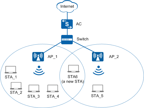
In Figure 1, AP_1 and AP_2 associate with an AC. Four users (STA_1 to STA_4) associate with AP_1, and one user (STA_5) associates with AP_2. If too many users connect to the Internet through AP_1, AP_1 will be overloaded, whereas resources on AP_2 are not used.

Load balancing can be implemented among APs only when the APs are connected to the same AC and all these APs can be discovered by a STA.
The load balancing algorithm described in this document applies only to Fit APs in V200R010C00 and later versions. For the load balancing algorithm support by Fit APs in V200R009C00, see the Product Documentation of the corresponding version.
Implementation
Static load balancing: APs providing the same services are manually added to a load balancing group. Each AP periodically reports STA association information to the AC, and the AC periodically distributes user traffic among APs based on received STA association information. Static load balancing can be implemented when the following conditions are met:
- APs in Figure 1 are single-band APs that support only one frequency band. If dual-band APs are used, traffic is load balanced among APs working on the same frequency band.
- Each load balancing group supports a maximum of 16 APs.
Dynamic load balancing: A STA sends broadcast Probe Request frames to scan available APs. The APs that receive the Probe Request frames all report the received STA information to the AC. The AC adds these APs to a load balancing group and then uses a load balancing algorithm to determine whether to steer the STA to access a lightly loaded AP. Static load balancing supports a limited number of group members, and all members must be manually added to the group and work on the same frequency band. Dynamic load balancing overcomes these limitations.
In the formula, the value of Maximum number of STAs allowed on the radio depends on AP types, which can be obtained using the display ap-type { id type-id | type ap-type } command. Maximum number of STAs allowed on the radio refers to the value of the field Maximum station number in the command output.
The following example explains the implementation of static load balancing.
As shown in Figure 1, four STAs (STA_1 to STA_4) are online on AP_1, and only STA_5 is online on AP_2. Assume that AP_1 and AP_2 each allows a maximum of 10 STAs, the start threshold for load balancing is set to 5, and the load difference threshold is set to 5%.
According to the load percentage calculation formula, the load percentage of AP_1's radio is 40% (4/10 x 100% = 40%), and the load percentage of AP_2's radio is 10% (1/10 x 100% = 10%). Therefore, the smallest load percentage value is 10%. The difference between the load percentage of AP_1 and the smallest value is 30% (40% - 10% = 30%), larger than the load difference threshold (5%). Therefore, the AC determines that traffic is not evenly distributed between the two APs, and starts the load balancing mechanism to steer some STAs from AP_1 to AP_2.