Neighbor Discovery
The Neighbor Discovery Protocol (NDP) is an enhancement of Address Resolution Protocol (ARP) and Internet Control Management Protocol (ICMP) router discovery in IPv4. In addition to ICMPv6 address resolution, NDP also provides the neighbor unreachable detection, duplicate address detection, redirection, ND proxy, and router discovery functions.
Address Resolution
In IPv4, a host needs to obtain the link-layer address of the destination host through the ARP protocol for communication. Similar to IPv4, the IPv6 NDP protocol parses the IP address to obtain the link-layer address.
- Layer 3 address resolution enables Layer 2 devices to use the same address resolution protocol.
- Layer 3 security mechanisms are used to prevent address resolution attacks.
- Request packets can be sent in multicast mode, reducing load on Layer 2 networks.
- In NS packets, the Type field value is 135 and the Code field value is 0. NS packets are similar to IPv4 ARP Request packets.
- In NA packets, the Type field value is 136 and the Code field value is 0. NA packets are similar to IPv4 ARP Reply packets.
Figure 1 shows the process of address resolution.
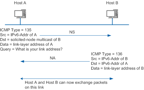
Host A needs to parse the link-layer address of Host B before sending packets to Host B. Host A sends an NS message with its IPv6 address as the source address and the solicited-node multicast address of Host B as the destination address. The Options field in the NS message carries the link-layer address of Host A.
After receiving the NS message, Host B replies with an NA Reply message. In the NA reply message, the source address is the IPv6 address of Host B, and the destination address is the IPv6 address of Host A (the NS message is sent to Host A in unicast mode using the link-layer address of Host A). The Options field carries the link-layer address of Host B. This is the whole address resolution process.
Neighbor Unreachable Detection
A neighbor state can transit from one to another. Hardware faults interrupt communication with neighboring devices. Communication cannot be restored if the destination of a neighboring device becomes invalid, but it can be restored if the path fails. Nodes need to maintain a neighbor table to monitor the state of each neighboring device.
There are five neighbor states: Incomplete, Reachable, Stale, Delay, and Probe.
Figure 2 shows the transition of neighbor states. The Empty state indicates that the neighbor table is empty.
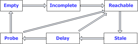
The following example describes changes in neighbor state of node A during its first communication with node B.
- Node A sends an NS message and generates a cache entry. The neighbor state of node A is Incomplete.
- If node B replies with an NA message, the neighbor state of node A changes from Incomplete to Reachable. Otherwise, the neighbor state changes from Incomplete to Empty after a certain period of time, and node A deletes this entry.
- After the neighbor reachable time times out, the neighbor state changes from Reachable to Stale, indicating that the neighbor reachable state is unknown.
- If node A in the Reachable state receives a non-NA Request message from node B, and the link-layer address of node B carried in the message is different from that learned by node A, the neighbor state of node A changes to Stale.
- Node A sends data to node B. The state of node A changes from Stale to Delay. Node A then sends an NS Request message.
- After a period of time, the neighbor state changes from Delay to Probe. During this time, if node A receives an NA Reply message, the neighbor state of node A changes to Reachable.
- Node A in the Probe state sends several unicast NS messages at the configured interval. If node A receives a Reply message, the neighbor state of node A changes from Probe to Reachable. Otherwise, the state changes to Empty and node A deletes the entry.
Duplicate Address Detection
Before an IPv6 unicast address is assigned to an interface, duplicate address detection (DAD) is performed to check whether another node uses the address. DAD is required if IP addresses are configured automatically. An IPv6 unicast address assigned to an interface but not verified by DAD is called a tentative address. An interface cannot use the tentative address for unicast communication but will join two multicast groups: ALL-nodes multicast group and Solicited-node multicast group.
IPv6 DAD is similar to IPv4 gratuitous ARP. A node sends an NS message that requests the tentative address as the destination address to the Solicited-node multicast group. If the node receives an NA Reply message, another node is using the tentative address for communication. This node will not use this tentative address for communication.
Figure 3 shows an example of DAD.
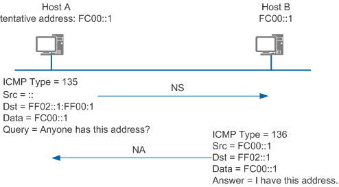
The IPv6 address FC00::1 is assigned to Host A as a tentative IPv6 address. To check the validity of this address, Host A sends an NS message containing the requested address FC00::1 to the Solicited-node multicast group to which FC00::1 belongs. Since FC00::1 is not specified, the source address of the NS message is an unspecified address. After receiving the NS message, Host B processes the message in one of the following ways:
If FC00::1 is a tentative address of Host B, Host B will not use this address as an interface address and will not send an NA message.
If FC00::1 is in use on Host B, Host B sends an NA message to FF02::1 carrying IP address FC00::1. In this way, Host A can find and mark the duplicate tentative address after receiving the message so it will not take effect.
Router Discovery
Router discovery is used to locate neighboring devices and learn their address prefixes and configuration parameters for address autoconfiguration.
IPv6 supports stateless address autoconfiguration. Hosts obtain IPv6 prefixes and automatically generate interface IDs. Router Discovery is the basis of IPv6 address autoconfiguration and is implemented through the following two types of packets:
- Router Advertisement (RA) message: Each router periodically sends multicast RA messages carrying network prefixes and identifiers on the network to declare its existence to Layer 2 hosts and devices. An RA message has a Type field value of 134.
- Router Solicitation (RS) message: After being connected to the network, a host immediately sends an RS message to obtain network prefixes. Devices on the network reply with RA messages. An RS message has a Type field value of 133.
Figure 4 shows the router discovery function.
Address Autoconfiguration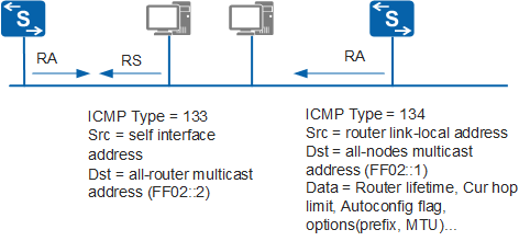
IPv4 uses DHCP to automatically configure IP addresses and default gateways. This simplifies network management. The length of an IPv6 address is increased to 128 bits. Multiple terminal nodes require the function of automatic configuration. IPv6 allows both stateful and stateless address autoconfiguration. Stateless autoconfiguration enables hosts to automatically generate link-local addresses. Hosts automatically configure global unicast addresses and obtain other information based on prefixes in the RA message.
The process of IPv6 stateless autoconfiguration is as follows:
- A host automatically configures the link-local address based on the interface ID.
- The host sends an NS message for duplicate address detection.
- If address conflict occurs, the host stops address autoconfiguration. Then addresses need to be configured manually.
- If addresses do not conflict, the link-local address takes effect. The host then connects to the network and communicates with the local node.
- The host either sends an RS message or receives RA messages devices periodically send.
- The host obtains the IPv6 address based on the prefixes carried in the RA message and the interface ID.
If there are multiple devices on the network where hosts reside, hosts need to select forwarding devices based on the destination address of the packet. In such a case, devices advertise default router priorities and route information, which allows hosts to select the optimal forwarding device based on the packet destination address.
The fields of default router priority and route information are defined in an RA message. These two fields enable hosts to select the optimal forwarding device.
After receiving an RA message containing route information, hosts update their routing tables. When sending packets to other devices, hosts check the routing table and select the optimal route.
When receiving an RA message carrying default router priorities, hosts update their default router lists. When sending packets to other devices, hosts select the device with the highest priority to forward packets from the router list. If the selected router does not work, hosts select the subsequent device in descending order of priority.
Redirection
To choose an optimal gateway device, the gateway device sends a Redirection message to notify the sender that another gateway device can send packets. Redirection messages are contained within ICMPv6 messages and have a Type field value of 137. They carry a better next hop address and destination address for packets that need to be redirected.
Figure 5 shows an example of packet redirection.
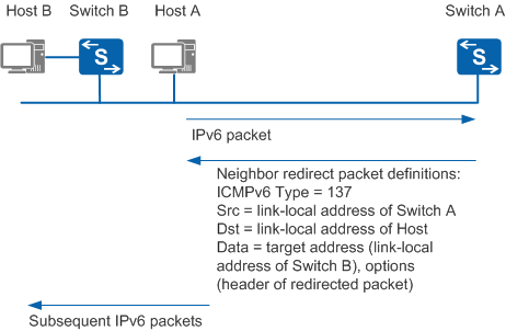
Host A needs to communicate with Host B. By default, Switch A sends packets from Host A to Host B. After receiving packets from Host A, Switch A discovers that sending packets directly to Switch B is more efficient. Switch A sends a Redirection message carrying the destination address of Host B to Host A to notify Host A that Switch B is a better next hop address. After receiving the Redirection message, Host A adds a host route to the default routing table. Packets sent to Host B will be sent directly to Switch B.
A device sends a Redirection message in the following situations:
- The destination address of the packet is not a multicast address.
- Packets are not forwarded to the device through routing.
- After route calculation, the outbound interface of the next hop is the interface that receives the packets.
- The device discovers that a better next hop IP address of the packet is on the same network segment as the source IP address of the packet.
- After checking the source address of the packet, the device discovers a neighboring device in the neighbor entries using this address as the global unicast address or the link-local unicast address.

If the communication target is a host, the IPv6 address of the host is used as the destination address of the Redirection message. If the Redirection message contains options, the link-layer address of the target host is included in the options.
ND Proxy
Generally, an IPv6 network is divided into multiple VLANs to enhance the security and flexibility of the networking. The hosts in a VLAN can directly communicate with each other, whereas the hosts in different VLANs cannot. Layer 2 isolation can be configured for ports in a VLAN so that ports in the same port isolation group are unreachable at Layer 2. However, user terminals require interconnection, that is, different VLANs or users isolated in a VLAN need to communicate with each other.
To resolve this issue, ND proxy can be deployed on an IPv6 network. (ND proxy is similar to ARP proxy on IPv4 networks.) Currently, switches support two ND proxy modes, as shown in Table 1.
ND Proxy Mode |
Application Scenario |
|---|---|
Intra-VLAN ND proxy |
Hosts that need to communicate with each other belong to the same network segment and same VLAN, but port isolation is configured in the VLAN. |
Inter-VLAN ND proxy |
Hosts that need to communicate with each other belong to the same network segment but different VLANs. |
Intra-VLAN ND proxy
On an IPv6 network, if port isolation is configured in a VLAN, users in the VLAN cannot communicate with each other. Configure intra-VLAN ND proxy on the VLAN-associated interface to enable Layer 3 communication among users.
As shown in Figure 6, Host_1 and Host_2 are two users on the device Switch. The two interfaces connected to Host_1 and Host_2 belong to VLAN 10 on the Switch.
Figure 6 Networking diagram of intra-VLAN ND proxy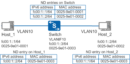
Host_1 and Host_2 cannot communicate at Layer 2 because VLAN port isolation is configured on the Switch.
However, with intra-VLAN ND proxy enabled on the Switch's interface, Host_1 and Host_2 can communicate at Layer 3. After an interface on the Switch receives an NS packet whose destination address is not its own address, the Switch does not discard the packet but searches for the neighbor entry matching the interface. If the neighbor entry of Host_2 exists, the Switch sends its MAC address to Host_1, and forwards the packet sent by Host_1 to Host_2. Otherwise, the Switch re-encapsulates an NS packet, and sends it to all interfaces in the VLAN except the interface that receives the NS packet. In this case, the Switch functions as the proxy of Host_2.
Inter-VLAN ND proxy
On an IPv6 network, if two hosts belong to the same network segment but different VLANs, to allow hosts to communicate with each other at Layer 3, you need to enable inter-VLAN ND proxy on the VLAN-associated interface (for example, an VLANIF interface or sub-interface).
Inter-VLAN ND proxies are generally applied to VLAN aggregation scenarios on IPv6 networks. When hosts in different sub-VLANs need to communicate at Layer 3, configure inter-VLAN ND proxy on the VLANIF interface corresponding the super-VLAN to allow communication among all sub-VLANs in the super-VLAN.
In Figure 7, Host_1 and Host_2 on the same network segment are connected to the Switch. Host_1 belongs to sub-VLAN 10, and Host_2 belongs to sub-VLAN 20.
Figure 7 Networking of inter-VLAN ND proxy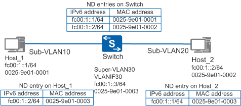
Host_1 and Host_2 belong to different sub-VLANs, so they cannot communicate at Layer 2.
However, with inter-VLAN ND proxy enabled on the Switch, Host_1 and Host_2 can communicate at Layer 3. After an interface on the Switch receives an NS packet whose destination address is not its own address, the Switch does not discard the packet but searches for the neighbor entry matching the interface. If the neighbor entry of Host_2 exists, the Switch sends its MAC address to Host_1, and forwards the packet sent by Host_1 to Host_2. Otherwise, the Switch re-encapsulates an NS packet, and sends it to all sub-VLAN interfaces except the interfaces in sub-VLAN 10. In this case, the Switch functions as the proxy of Host_2.