Example for Configuring Routed Proxy ARP
Overview
When an enterprise network is divided into subnets, two subnets may belong to the same network segment but different physical networks. These two subnets are isolated by the switch. You can modify the routing information about the hosts on the network, so that the data packets destined for other subnets are sent to the gateway connected to different subnets and then forwarded by the gateway to the destination. However, to implement this solution, you must configure routes for all hosts on the subnets. This complicates management and maintenance.
Deploying routed proxy ARP on the gateway can effectively solve the management and maintenance problems in subnet division. Routed proxy ARP allows the communication between the hosts whose IP addresses belong to the same network segment but different physical networks. In addition, the default gateway does not need to be configured on the hosts, facilitating management and maintenance.
Configuration Notes
After routed proxy ARP is enabled on the device, reduce the aging time of ARP entries on hosts. In this way, the invalid ARP entries do not take effect as soon as possible, reducing the number of packets that are sent to but cannot be forwarded by the switch.
For applicable product models and versions, see Applicable Product Models and Versions.

For details about software mappings, visit Hardware Query Tool and search for the desired product model.
Networking Requirements
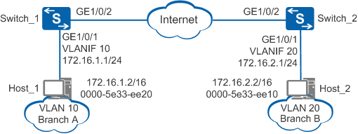
As shown in Figure 1, branch A and branch B of the enterprise are located in different cities and their host IP addresses belong to the same network segment 172.16.0.0/16. There are reachable routes between Switch_1 connected to branch A and Switch_2 connected to branch B. Branch A and branch B belong to different broadcast domains; therefore, they cannot communicate on a LAN. Hosts in the branches are not configured with default gateway addresses, so they cannot communicate across network segments. The enterprise requires that branch A and branch B communicate without changing the host configurations.
Configuration Roadmap
The configuration roadmap is as follows:
Add the interface connecting Switch_1 and branch A to VLAN 10 and add the interface connecting Switch_2 and branch B to VLAN 20.
Enable routed proxy ARP on VLANIF interfaces of branch A and branch B to allow the two branches to communicate.
Procedure
- Create VLANs, add interfaces to VLANs, and configure IP addresses for the interfaces.
# Configure Switch_1.
<HUAWEI> system-view
[HUAWEI] sysname Switch_1
[Switch_1] vlan batch 10
[Switch_1] interface gigabitethernet 1/0/1
[Switch_1-GigabitEthernet1/0/1] port link-type access
[Switch_1-GigabitEthernet1/0/1] port default vlan 10
[Switch_1-GigabitEthernet1/0/1] quit
[Switch_1] interface vlanif 10
[Switch_1-Vlanif10] ip address 172.16.1.1 24
# Configure Switch_2.
<HUAWEI> system-view
[HUAWEI] sysname Switch_2
[Switch_2] vlan batch 20
[Switch_2] interface gigabitethernet 1/0/1
[Switch_2-GigabitEthernet1/0/1] port link-type access
[Switch_2-GigabitEthernet1/0/1] port default vlan 20
[Switch_2-GigabitEthernet1/0/1] quit
[Switch_2] interface vlanif 20
[Switch_2-Vlanif20] ip address 172.16.2.1 24
- Configure routed proxy ARP.
# Configure Switch_1.
[Switch_1-Vlanif10] arp-proxy enable  //Configure routed proxy ARP
[Switch_1-Vlanif10] quit
# Configure Switch_2.
[Switch_2-Vlanif20] arp-proxy enable  //Configure routed proxy ARP
[Switch_2-Vlanif20] quit
- Verify the configuration.
# Check ARP entries of VLANIF 10 on Switch_1. The command output shows the MAC address mapping the IP address of VLANIF 10.
[Switch_1] display arp interface vlanif 10
IP ADDRESS      MAC ADDRESS     EXPIRE(M) TYPE        INTERFACE   VPN-INSTANCE
                                          VLAN/CEVLAN
------------------------------------------------------------------------------
172.16.1.1      101b-5441-5bf6            I -         Vlanif10
------------------------------------------------------------------------------
Total:1         Dynamic:0       Static:0     Interface:1
# Select Host_1 (using Windows 7 as an example) at 172.16.1.2/16 in branch A and select Host_2 at 172.16.2.2/16 in branch B. Ping the IP address of Host_2 on Host_1. The ping operation is successful.
C:\Documents and Settings\Administrator> ping 172.16.2.2
Pinging 172.16.2.2 with 32 bytes of data:
Reply from 172.16.2.2: bytes=32 time<1ms TTL=128
Reply from 172.16.2.2: bytes=32 time<1ms TTL=128
Reply from 172.16.2.2: bytes=32 time<1ms TTL=128
Reply from 172.16.2.2: bytes=32 time<1ms TTL=128

Ping statistics for 172.16.2.2:
    Packets: Sent = 4, Received = 4, Lost = 0 (0% loss),
Approximate round trip times in milli-seconds:
    Minimum = 0ms, Maximum = 0ms, Average = 0ms
# Check the ARP table on Host_1. The command output shows that the MAC address mapping the IP address of Host_2 is the MAC address of VLANIF 10 on Switch_1, indicating that Host_1 and Host_2 can communicate with each other through ARP proxy.
C:\Documents and Settings\Administrator> arp -a
Interface: 172.16.1.2 --- 0xd
  Internet Address      Physical Address      Type
  172.16.2.2            101b-5441-5bf6        dynamic
...
Configuration Files
Switch_1 configuration file
# sysname Switch_1 # vlan batch 10 # interface Vlanif10 ip address 172.16.1.1 255.255.255.0 arp-proxy enable # interface GigabitEthernet1/0/1 port link-type access port default vlan 10 # returnSwitch_2 configuration file
#
sysname Switch_2
#
vlan batch 20
#
interface Vlanif20
 ip address 172.16.2.1 255.255.255.0
 arp-proxy enable
#
interface GigabitEthernet1/0/1
 port link-type access
 port default vlan 20
#
return
Applicable Product Models and Versions
Series |
Product Model |
Software Version |
|---|---|---|
S2700 |
S2700-EI |
V100R006C05 |
S2710-SI |
V100R006C05 |
|
S2720-EI |
V200R006C10, V200R009C00, V200R010C00, V200R011C10, V200R012C00, V200R013C00, V200R019C00, V200R019C10 |
|
S2750-EI |
V200R005C00SPC300, V200R006C00, V200R007C00, V200R008C00, V200R009C00, V200R010C00, V200R011C00, V200R011C10, V200R012C00 |
|
S3700 |
S3700-SI, S3700-EI |
V100R006C05 |
S3700-HI |
V200R001C00 |
|
S5700 |
S5700-LI |
V200R005C00SPC300, V200R006C00, V200R007C00, V200R008C00, V200R009C00, V200R010C00, V200R011C00, V200R011C10, V200R012C00 |
S5700S-LI |
V200R005C00SPC300, V200R006C00, V200R007C00, V200R008C00, V200R009C00, V200R010C00, V200R011C00, V200R011C10, V200R012C00 |
|
S5700-SI |
V200R001C00, V200R002C00, V200R003C00, V200R005C00 |
|
S5700-EI |
V200R001(C00&C01), V200R002C00, V200R003C00, V200R005(C00&C01&C02&C03) |
|
S5700-HI |
V200R001(C00&C01), V200R002C00, V200R003C00, V200R005(C00SPC500&C01&C02) |
|
S5710-C-LI |
V200R001C00 |
|
S5710-X-LI |
V200R008C00, V200R009C00, V200R010C00, V200R011C00, V200R011C10, V200R012C00 |
|
S5710-EI |
V200R001C00, V200R002C00, V200R003C00, V200R005(C00&C02) |
|
S5710-HI |
V200R003C00, V200R005(C00&C02&C03) |
|
S5720-LI, S5720S-LI |
V200R010C00, V200R011C00, V200R011C10, V200R012(C00&C20), V200R013C00, V200R019C00, V200R019C10 |
|
S5720-SI, S5720S-SI |
V200R008C00, V200R009C00, V200R010C00, V200R011C00, V200R011C10, V200R012C00, V200R013C00, V200R019C00, V200R019C10 |
|
S5720I-SI |
V200R012C00, V200R013C00, V200R019C00, V200R019C10 |
|
S5720-EI |
V200R007C00, V200R008C00, V200R009C00, V200R010C00, V200R011C00, V200R011C10, V200R012C00, V200R013C00, V200R019C00, V200R019C10 |
|
S5720-HI |
V200R006C00, V200R007(C00&C10), V200R008C00, V200R009C00, V200R010C00, V200R011C00, V200R011C10, V200R012C00, V200R013C00, V200R019C00, V200R019C10 |
|
S5730-HI |
V200R012C00, V200R013C00, V200R019C00, V200R019C10 |
|
S5730-SI |
V200R011C10, V200R012C00, V200R013C00, V200R019C00, V200R019C10 |
|
S5730S-EI |
V200R011C10, V200R012C00, V200R013C00, V200R019C00, V200R019C10 |
|
S5731-H |
V200R013C02, V200R019C00, V200R019C10 |
|
S5731-S, S5731S-S |
V200R019C00, V200R019C10 |
|
S5731S-H |
V200R019C00, V200R019C10 |
|
S5732-H |
V200R019C00, V200R019C10 |
|
S5735-L, S5735S-L |
V200R019C00, V200R019C10 |
|
S5735S-L-M |
V200R019C00, V200R019C10 |
|
S5735-S, S5735S-S |
V200R019C00, V200R019C10 |
|
S5700 |
S5735-S-I |
V200R019C10 |
S6700 |
S6700-EI |
V200R001(C00&C01), V200R002C00, V200R003C00, V200R005(C00&C01&C02) |
S6720-LI, S6720S-LI |
V200R011C00, V200R011C10, V200R012C00, V200R013C00, V200R019C00, V200R019C10 |
|
S6720-SI, S6720S-SI |
V200R011C00, V200R011C10, V200R012C00, V200R013C00, V200R019C00, V200R019C10 |
|
S6720-EI |
V200R008C00, V200R009C00, V200R010C00, V200R011C00, V200R011C10, V200R012C00, V200R013C00, V200R019C00, V200R019C10 |
|
S6720S-EI |
V200R009C00, V200R010C00, V200R011C00, V200R011C10, V200R012C00, V200R013C00, V200R019C00, V200R019C10 |
|
S6720-HI |
V200R012C00, V200R013C00, V200R019C00, V200R019C10 |
|
S6730-H |
V200R013C02, V200R019C00, V200R019C10 |
|
S6730-S, S6730S-S |
V200R019C00, V200R019C10 |
|
S6730S-H |
V200R019C10 |
|
S7700 |
S7703, S7706, S7712 |
V200R001(C00&C01), V200R002C00, V200R003C00, V200R005C00, V200R006C00, V200R007C00, V200R008C00, V200R009C00, V200R010C00, V200R011C10, V200R012C00, V200R013C00, V200R013C02, V200R019C00, V200R019C10 |
S7703 PoE |
V200R013C00, V200R019C00, V200R019C10 |
|
S7706 PoE |
V200R013C00, V200R019C00, V200R019C10 |
|
S9700 |
S9703, S9706, S9712 |
V200R001(C00&C01), V200R002C00, V200R003C00, V200R005C00, V200R006C00, V200R007(C00&C10), V200R008C00, V200R009C00, V200R010C00, V200R011C10, V200R012C00, V200R013C00 |